Rotation device for a boom of a mining or constructions work rig, rig and boom

a technology of a rig and a boom, which is applied in the direction of machine supports, cutting machines, domestic objects, etc., can solve the problems of difficult to make it possible to position with high precision and impossible to adjust with high precision

Active Publication Date: 2012-09-18
EPIROC ROCK DRILLS AB
View PDF9 Cites 2 Cited by
  • Summary
  • Abstract
  • Description
  • Claims
  • Application Information

AI Technical Summary

Benefits of technology

[0006]Through one embodiment of the invention, wherein the first rotation unit provides a separating place at its outgoing rotational axis, there is achieved a possibility of having a releasable connection with a boom, which i.a. gives the advantage that the same boom, and the same mining or constructions work rig can be easily employed for different uses, wherein the equipment to be used is connectable at said separating place.
[0007]By also providing a separating place at the second rotation unit, the corresponding advantages are achieved, and further more that the whole rotation device is releasable from the boom and the equipment and thereby easily exchangeable and / or removable for service.
[0008]By providing the rotation device / angular device with an open or openable intermediate portion, simple access is possible from the outside of the respective rotation actuator for service, exchange etc.
[0009]By providing a toothed transmission unit, and in particular a planet gear transmission unit for transmitting the movement of the respective rotation actuator, the simplicity and compactness of the device is accentuated.
[0010]According to the invention, the boom portions can advantageously be manufactured with non-circular cross section so that the complete boom can be made more rigid and with more loading capacity and be less susceptible to play.
[0011]The corresponding advantages are achieved according to the invention in a rig and a boom including such a rotation device.

Problems solved by technology

The known device, however, makes it more difficult to make it possible to position with high precision, which is more and more essential for today's users.
Because of the positioning and the arrangement of the first rotation motor, a certain rotational deviation that can not be neglected will be the result of play and deformation, which in practice makes it impossible to adjust with high precision.

Method used


Image

  • Rotation device for a boom of a mining or constructions work rig, rig and boom
  • Rotation device for a boom of a mining or constructions work rig, rig and boom
  • Rotation device for a boom of a mining or constructions work rig, rig and boom

Examples


Embodiment Construction

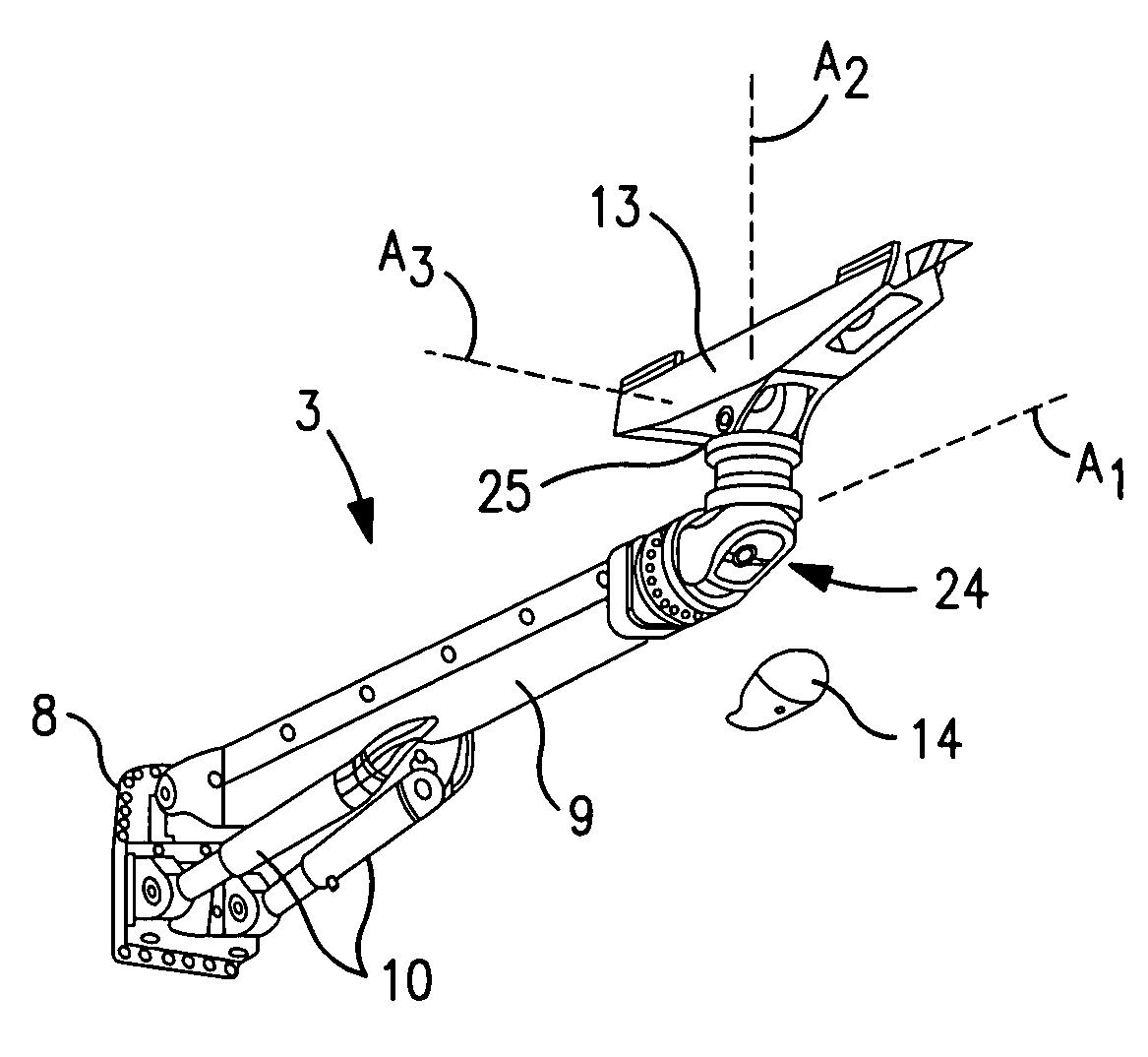
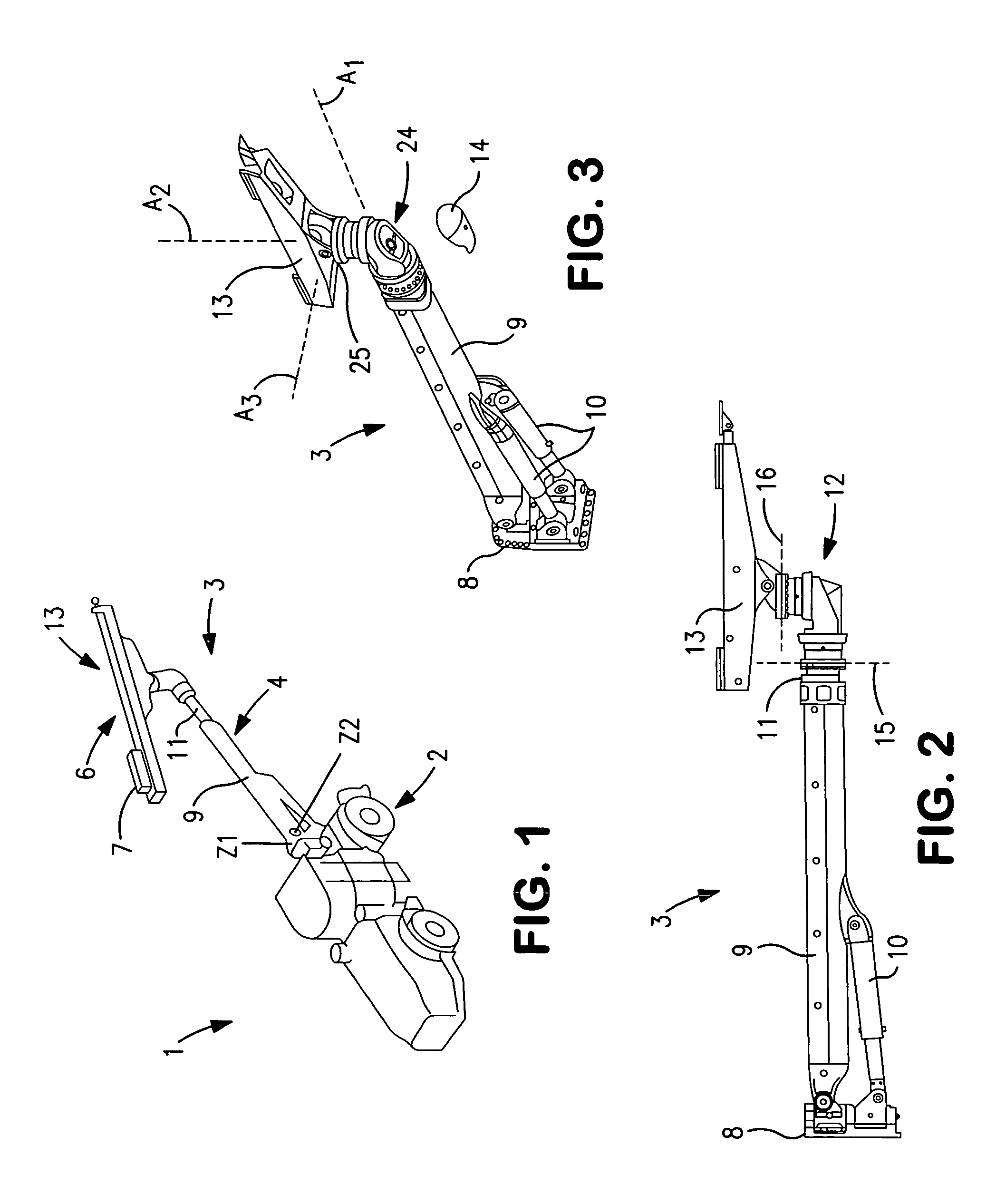
[0017]In FIG. 1 reference numeral 1 in general concerns a rig in the form of a mining machine, which in this case is a machine for drilling of a blast hole and for applying rock reinforcements respectively. The mining machine 1 includes a carrier 2 having conventional driving arrangements and an operator cabin, wherein a boom device 3 is attached to the carrier. The boom device 3 includes a telescopic and liftable and lowerable boom 4, at the outer end of which being fastened equipment 13 for e.g. rock drilling, including a feeder 6 and a rock drilling machine 7. Z1 and Z2 indicate rotational axes for the boom device. Further rotational axes are described in the following.

[0018]FIG. 2 shows the boom device 3 in greater detail including a carrier attachment 8 and the telescopic boom, which includes a first boom portion 9 and a second boom portion 11 which is almost entirely retracted in the Figure (see the boom portions more drawn apart in FIG. 1). The boom 9, 11 is manoeuvred for li...


PUM


Abstract

A rotation device (12) for rotation of equipment (13) fastened at the region of a distal end of a boom (9,11), which has a general longitudinal axis, and which is part of a boom device (3) which is fastenable to a carrier (2) for a mining or constructions work rig, wherein the rotation device includes a first rotation unit (R1) arranged to rotate the equipment around an axis (A1) which is essentially parallel to the longitudinal axis of the boom and a second rotation unit (R2) which is arranged to rotate the equipment around an axis (A2), which forms an angle with the longitudinal axis of the boom. The rotation units (R1, R2) are fastened to an angle unit (12′), which is included in the rotation device (12) and has rotational axes (A1, 21; A2,22) extending at an angle with respect to each other, and are connectable to the boom (9,11) as well as to said equipment (13). The invention also concerns a mining or constructions work rig and a boom.

Description

FIELD OF THE INVENTION[0001]The invention concerns a rotation device for a boom of a mining or construction work rig. The invention also concerns a rig and a boom including such a rotation device.BACKGROUND OF THE INVENTION[0002]From EP-B1-0 434 652, such a device is previously known in a telescopic boom arrangement, wherein a rotation motor at a rear end of a first boom portion is arranged to rotate a second boom portion. A rotation motor is positioned at the outer end of a second boom portion, which allows rotation of a feed beam for a rock drilling machine.[0003]Through this arrangement, the rock drilling boom is maneuverable such that an operator can relatively easily position the feed beam in the desired position and direction with six degrees of freedom. The known device, however, makes it more difficult to make it possible to position with high precision, which is more and more essential for today's users. Because of the positioning and the arrangement of the first rotation m...

Claims


Application Information

Patent Timeline
Patent Type & Authority Patents(United States)
IPC IPC(8): E21C25/06
CPCE21B7/028E21B7/025E21B7/02
Inventor SAF, FREDRIK
Owner EPIROC ROCK DRILLS AB
Why Eureka
Try Eureka