Telescopic tool

a telescopic tool and handle technology, applied in the field of telescopic tools, can solve the problems of not allowing the user to hold the coupling sleeve, and the telescopic tool does not allow the user to change the working portion on the front end of the handle, so as to achieve the effect of reliable locking effect and easy operation of the switch controller

Active Publication Date: 2022-03-01
HONG ANN TOOL INDS
View PDF15 Cites 2 Cited by
  • Summary
  • Abstract
  • Description
  • Claims
  • Application Information

AI Technical Summary

Benefits of technology

[0004]An objective of the present invention is to provide a telescopic tool including a positioning device mounted between a first rod and a second rod to thereby provide a reliable locking effect. Furthermore, both hands of a user can grip a first gripping portion and a second gripping portion, respectively, thereby permitting easy operation of a switch controller.
[0015]Thus, the telescopic tool according to the present invention uses the positioning device to avoid unexpected loosening. Furthermore, the first gripping portion and the second gripping portion can be respectively held by two hands of the user while easily controlling the switch controller to switch between the locking position and the releasing position.

Problems solved by technology

However, this telescopic tool does not allow a user to hold the coupling sleeve.
Furthermore, this telescopic tool does not allow a change of a working portion on a front end of the handle.

Method used


Image

  • Telescopic tool
  • Telescopic tool
  • Telescopic tool

Examples


Embodiment Construction

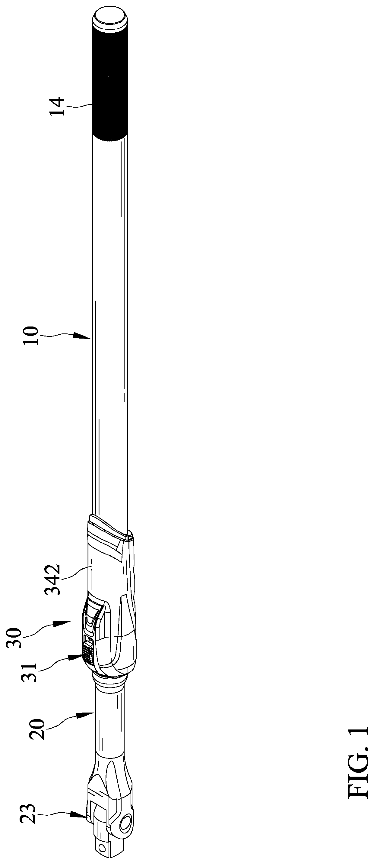
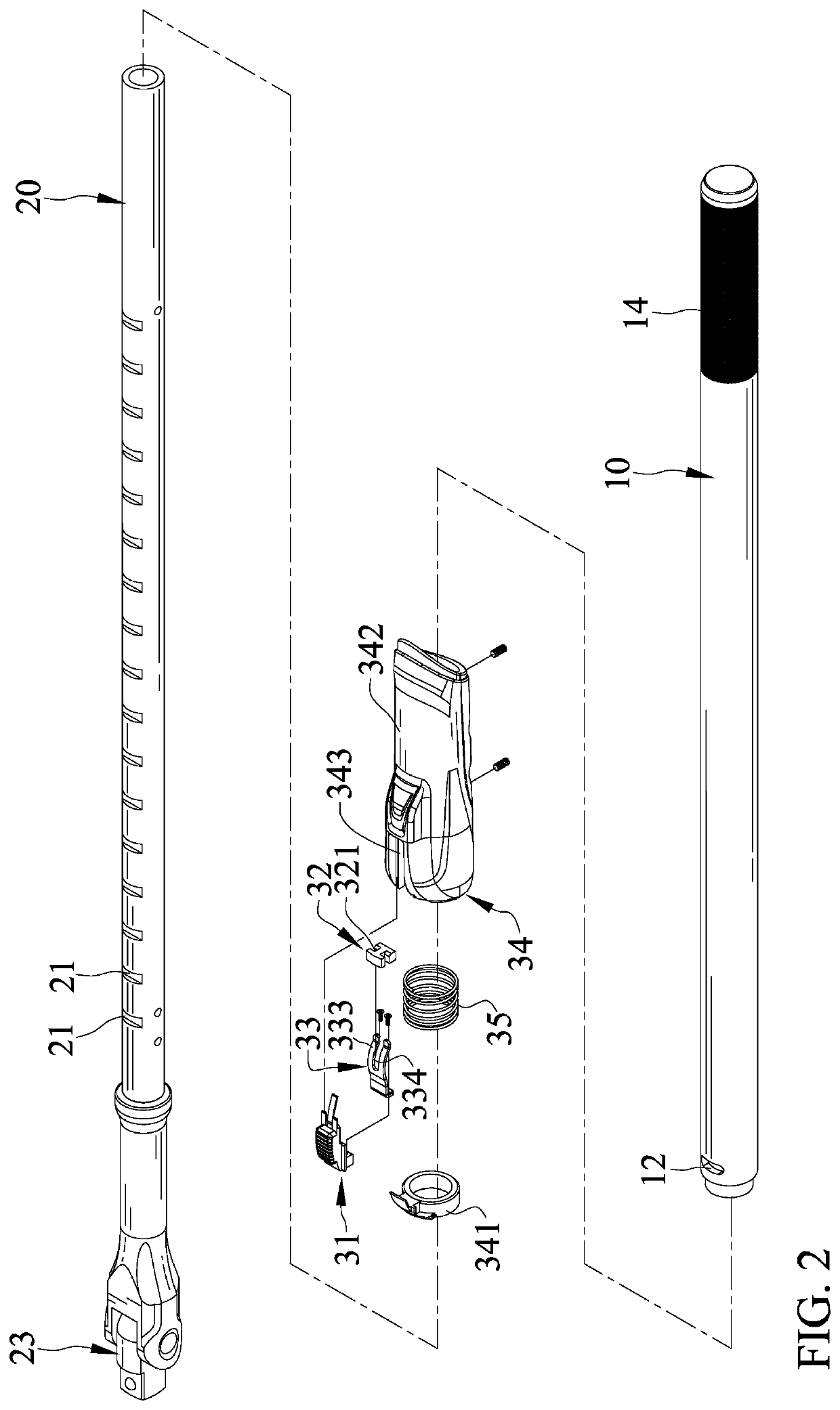
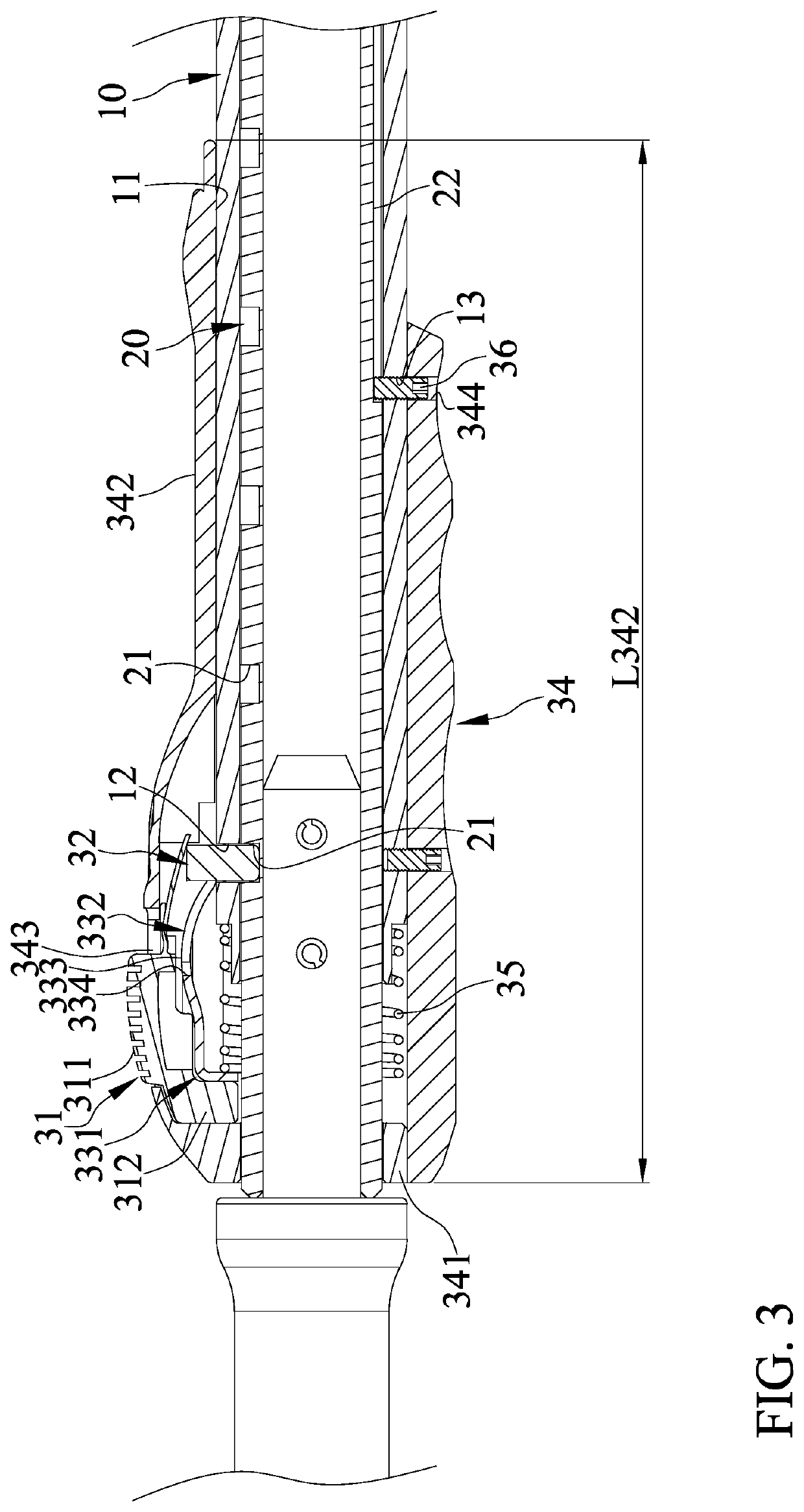
[0023]With reference to FIGS. 1-4, a telescopic tool of an embodiment according to the present invention includes a first rod 10, a second rod 20, and a positioning device 30 mounted between the first rod 10 and the second rod 20. The first rod 10 includes a longitudinal hole 11, a first positioning hole 12, a first through-hole 13, and a first gripping portion 14. The longitudinal hole 11 extends through at least one end of the first rod 10 along a longitudinal axis of the first rod 10. The first positioning hole 12 extends through an outer periphery of the first rod 10 in a radial direction perpendicular to the longitudinal axis and intercommunicates with the longitudinal hole 11. The first through-hole 13 extends through the outer periphery of the first rod 10 in a radial direction perpendicular to the longitudinal axis, intercommunicates with the longitudinal hole 11, and is located on a side of the first rod 10 opposite to the first positioning hole 12. The first gripping porti...


PUM


Abstract

A telescopic tool includes a positioning device mounted between first and second rods. The first rod includes a longitudinal hole extending along a longitudinal axis, a first positioning hole intercommunicating with the longitudinal hole, and a first gripping portion. The second rod is movably received in the longitudinal hole, includes a plurality of second positioning holes, and is movable relative to the first rod along the longitudinal axis to align the first positioning hole with one of the plurality of second positioning holes. A switch controller is movable relative to the first rod and is movably coupled to a positioning member. The positioning member movably extends through the first hole and is releasably engaged in one of the plurality of second positioning holes in response to movement of the switch controller relative to the first rod. A fixing member includes a second gripping portion mounted around the first rod.

Description

BACKGROUND OF THE INVENTION[0001]The present invention relates to a telescopic tool and, more particularly, to a telescopic tool permitting gripping by both hands of a user.[0002]Currently available telescopic tools, an example of which is disclosed in Taiwan Patent Publication No. 554799, include a handle for a hand tool, a coupling sleeve, and an extension rod. The extension rod is hollow to permit insertion of a handle. The extension rod extends into and is positioned in an end of the coupling sleeve. The other end of the coupling sleeve includes an eccentric inner wall. A ring is received and restrained by the eccentric inner wall to prevent outward movement. The ring includes an outer periphery having two arcuate raised portions between which a pressing pin is pivotably mounted. The handle extends into the coupling sleeve and the extension rod. The ring is mounted around the handle. When the handle or the extension rod is rotated, the ring pivots at the eccentric inner wall of ...

Claims


Application Information

Patent Timeline
Patent Type & Authority Patents(United States)
IPC IPC(8): B25B23/00B25G1/04
CPCB25B23/0021B25G1/043
Inventor SU, CHENG-WEI
Owner HONG ANN TOOL INDS
Why Eureka
Try Eureka