
Robot system and coupling method

a robot system and coupling technology, applied in the direction of unstripped conductor connection apparatus, program control, instruments, etc., can solve the problems of failure of coupling work and difficulty in accurately inserting the ffc into the connector

Active Publication Date: 2022-03-08
SEIKO EPSON CORP
View PDF7 Cites 2 Cited by
  • Summary
  • Abstract
  • Description
  • Claims
  • Application Information

AI Technical Summary

Problems solved by technology

However, in the robot disclosed in JP-A-2017-224527, there is a problem that, for example, when the gripping position of the FFC by the gripping mechanism is inaccurate, it is difficult to accurately insert the FFC into the connector and, as a result, the coupling work is failed.

Method used


Image

  • Robot system and coupling method
  • Robot system and coupling method
  • Robot system and coupling method

Examples


modified example 1

[0101]FIG. 22 is the block diagram showing modified example 1 with the focus on hardware of the robot system.

[0102]FIG. 22 shows an overall configuration of a robot system 100B in which a computer 63 is directly coupled to the robot 1. The control of the robot 1 is directly executed by reading commands in a memory using a processor in the computer 63.

[0103]Therefore, the computer 63 may be regarded as “control apparatus 200”.

modified example 2

[0104]FIG. 23 is the block diagram showing modified example 2 with the focus on hardware of the robot system.

[0105]FIG. 23 shows an overall configuration of a robot system 100C in which the robot 1 containing the controller and a computer 66 are coupled and the computer 66 is coupled to a cloud 64 via a network 65 such as a LAN. The control of the robot 1 may be executed by reading commands in a memory using a processor in the computer 66 or executed via the computer 66 by reading commands in a memory using a processor on the cloud 64.

[0106]Therefore, one, two, or three of the controller 61, the computer 66, and the cloud 64 may be regarded as “control apparatus 200”.

[0107]As above, the robot system and coupling method according to the present disclosure are explained with respect to the illustrated embodiments, however, the present disclosure is not limited to those. The respective parts forming the robot system may be replaced by arbitrary configurations that may fulfill the same ...


PUM


Abstract

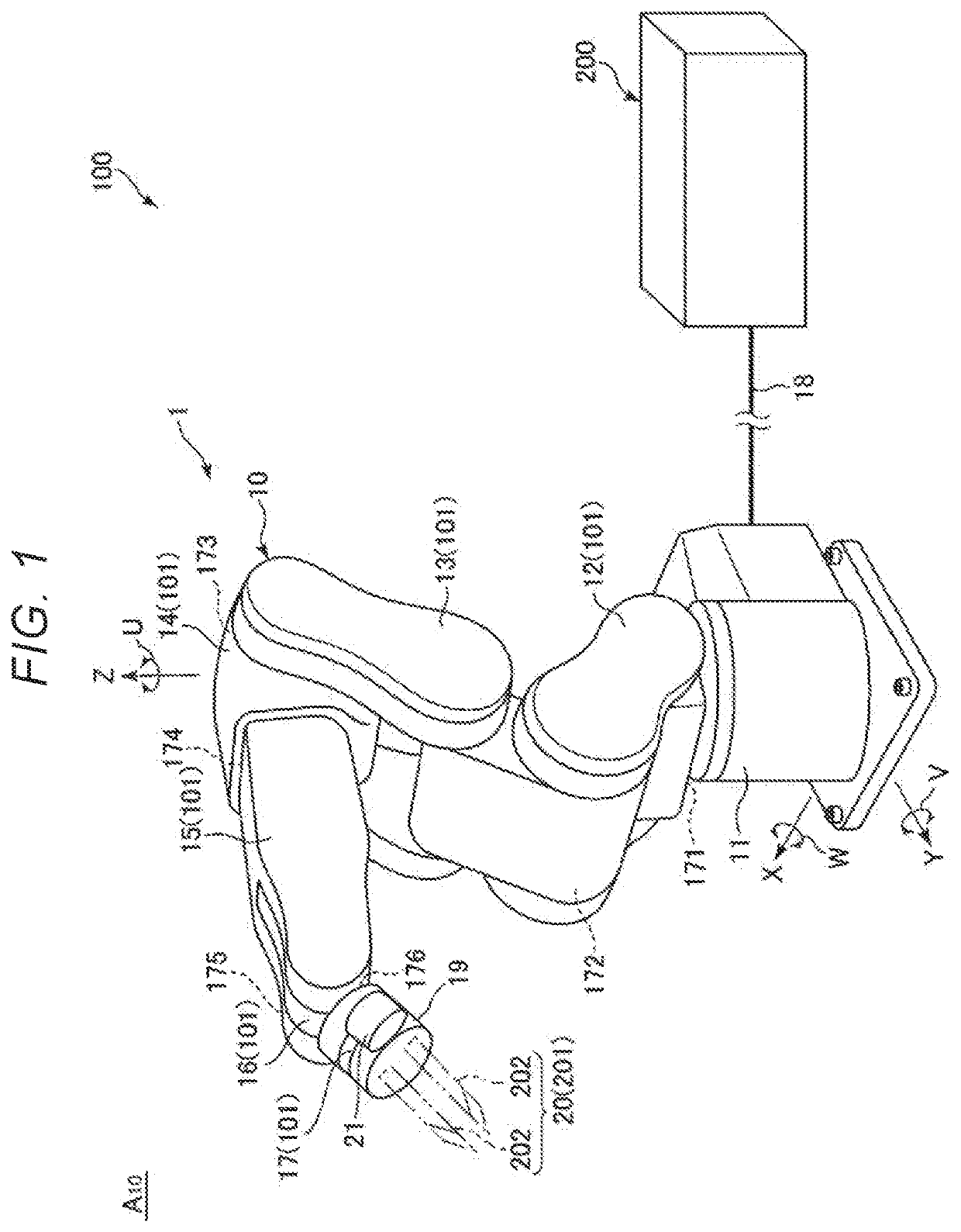
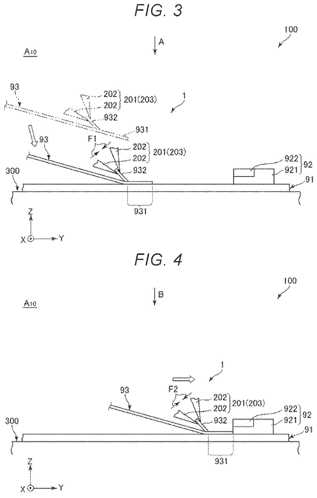
A robot system that performs work of coupling a cable to a connector provided on a board, includes a robot in which a gripping unit that grips the cable and a force detection unit that detects a force acting on the gripping unit are provided, and a robot control apparatus that controls the robot, wherein the robot control apparatus controls the robot to perform a conveyance action for the gripping unit to grip the cable with a first gripping force and convey the cable onto the board, a correction action for the gripping unit to grip the cable with a second gripping force and correct a posture of the cable based on the force acting by pressing the cable against the connector, and an insertion action for the gripping unit to grip the cable with a third gripping force and insert the cable into the connector.

Description

[0001]The present application is based on, and claims priority from, JP Application Serial Number 2018-215966, filed Nov. 16, 2018, the disclosure of which is hereby incorporated by reference herein in its entirety.BACKGROUND1. Technical Field[0002]The present disclosure relates to a robot system and coupling method.2. Related Art[0003]For example, JP-A-2017-224527 discloses a single-arm robot including a base and a single arm. The robot disclosed in JP-A-2017-224527 has a gripping mechanism for gripping an FFC (Flexible Flat Cable) attached to the distal end portion of the arm, and may perform coupling work of inserting and coupling the FFC into a connector in the attachment state.[0004]However, in the robot disclosed in JP-A-2017-224527, there is a problem that, for example, when the gripping position of the FFC by the gripping mechanism is inaccurate, it is difficult to accurately insert the FFC into the connector and, as a result, the coupling work is failed.SUMMARY[0005]The pre...

Claims


Application Information

Patent Timeline
Patent Type & Authority Patents(United States)
IPC IPC(8): B25J9/16B25J15/00B25J9/10
CPCB25J9/1687B25J9/1015B25J9/1633B25J9/1674B25J9/1697B25J15/0004B25J9/1679B25J9/1602G05B2219/39506B25J13/085B25J19/023H01R43/205H01R12/62H01R43/01
Inventor UEDA, JUNYAHATA, HIDEKIMIYASAKA, MASAKI
Owner SEIKO EPSON CORP
Learn More