Disconnectable tower yoke mooring system and methods for using same
a technology of disconnection and tower yoke, which is applied in the direction of anchoring arrangements, mooring equipment, vessel construction, etc., can solve the problems of large system size and complexity, inability to adapt to harsh offshore environments, and the need for a swivel stack associated with fluid, gas, chemical, etc., to timely disconnect the vessel
- Summary
- Abstract
- Description
- Claims
- Application Information
AI Technical Summary
Problems solved by technology
Method used
Image

Examples
embodiment 1
[0066]2. The method of embodiment 1, further comprising mechanically linking the ballast tank and the second end of the yoke to the support structure.
[0067]3. The method of embodiments 1 or 2, wherein the support structure comprises a generally vertical portion and a cantilevered generally horizontal portion.
[0068]4. The method according to any embodiment 1 to 3, wherein the first winch system is located on the cantilevered generally horizontal portion of the support structure.
[0069]5. The method according to any embodiment 1 to 4, wherein releasing the tower connector from the yoke head connector comprises releasing pressure in a hydraulic cylinder to disconnect a collet connection between the yoke head connector and the tower connector.
[0070]6. The method according to any embodiment 1 to 5, further comprising applying thrust to the vessel, prior to releasing the tower connector from the yoke head.
[0071]7. The method according to any embodiment 1 to 6, wherein the first winch syste...
embodiment 11
[0076]12. The method of embodiment 11, further comprising applying thrust to the vessel, prior to releasing the tower connector from the yoke head connector.
[0077]13. The method of embodiments 11 or 12, further comprising mechanically linking the ballast tank and the second end of the yoke to the support structure
[0078]14. The method according to any embodiment 11 to 13, wherein the support structure comprises a generally vertical portion and a cantilevered generally horizontal portion and wherein the first winch system is located on the cantilevered generally horizontal portion of the support structure.
[0079]15. The method according to any embodiment 11 to 14, wherein releasing the tower connector from the yoke head connector comprises releasing pressure in a hydraulic cylinder to disconnect a collet connection between the yoke head connector and the tower connector.
[0080]16. The method according to any embodiment 11 to 15, wherein the first winch system is located above the ballas...
embodiment 20
[0085]21. The method , wherein the third winch system comprises a spring line winch system.
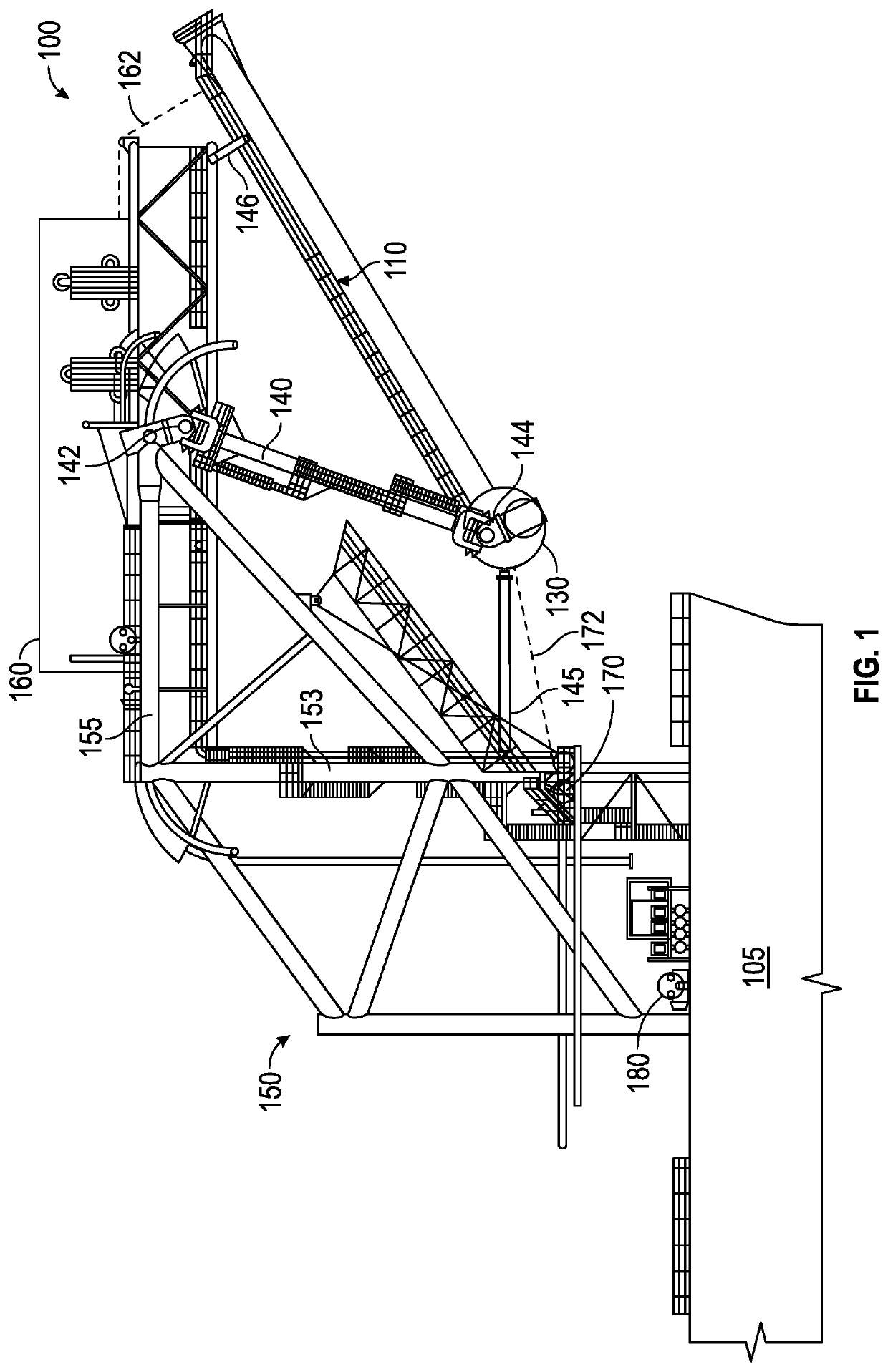
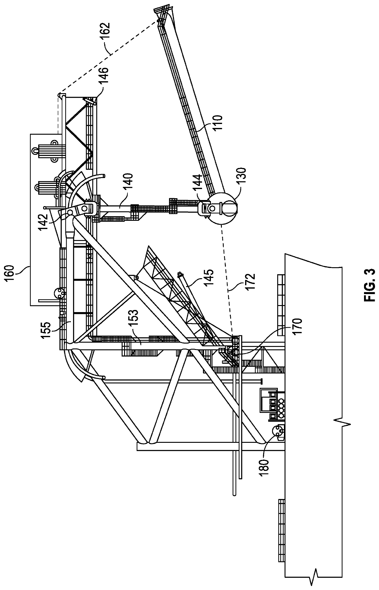
[0086]22. A method for disconnecting a floating vessel moored to a tower structure at sea, comprising: providing a floating vessel comprising a support structure mounted on an upper deck thereof; one or more extension arms suspended from the support structure; a ballast tank connected to the one or more extension arms, the ballast tank configured to oscillate back and forth underneath the support structure; a yoke extending from and connected to the ballast tank at a first end thereof, the yoke comprising a tower connector disposed on a second end thereof; a first winch system located on the support structure, the first winch system connected to the yoke proximate the second end of the yoke via a first line or cable for controlling vertical movement of the yoke; a second winch system connected to the ballast tank via a second line or cable for controlling back and forth horizontal movement of ...
PUM
 Abstract
Description
Claims
Application Information
 - R&D Engineer
- R&D Manager
- IP Professional
- Industry Leading Data Capabilities
- Powerful AI technology
- Patent DNA Extraction
Browse by: Latest US Patents, China's latest patents, Technical Efficacy Thesaurus, Application Domain, Technology Topic.
© 2024 PatSnap. All rights reserved.Legal|Privacy policy|Modern Slavery Act Transparency Statement|Sitemap