Method for lifting and transporting a heavy load using a fly-jib

a technology of heavy loads and fly-jibs, which is applied in the direction of floating buildings, underwater structures, artificial islands, etc., can solve the problems of increasing the risk of loss, increasing the risk of damage to cargo and workers, and inconvenient methods, etc., to achieve the effect of increasing the reach and height of the heavy lifting cran

Inactive Publication Date: 2005-08-23
KRABBENDAM RICHARD L
View PDF6 Cites 30 Cited by
  • Summary
  • Abstract
  • Description
  • Claims
  • Application Information

AI Technical Summary

Benefits of technology

[0007]The invention relates to a method for lifting and transporting a heavy load using a heavy lift vessel with at least two heavy lift cranes, wherein a fly-jib module is mounted on the heavy lift crane to increase reach and height of the heavy lift cranes. The method entails picking up a load from a first location using the fly-jib modules simultaneously, shifting the load from the first location to over a second location, wherein the second location is on the heavy lift vessel; and placing the load on the second location. The heavy lift vessel, then, moves from the first position to second position. A mooring system is used to maintain the heavy lift vessel at the second position. The method ends by picking up the load from the second location using the first and second fly-jib modules simultaneously; shifting the load from a second location to over a third location; and placing the load on the third location.

Problems solved by technology

Transportation problems compound and the risk of loss increases as the cargo becomes heavier, requiring heavy lift cranes.
These methods are inconvenient, time-consuming, and costly to move heavy structures from one location to another.
Since the use of multiple vessels and barges increases the risk of damage to the cargo and workers, a need exists for a heavy lift vessel that can self-load, transport, and install cargo in one vessel.

Method used


Image

  • Method for lifting and transporting a heavy load using a fly-jib
  • Method for lifting and transporting a heavy load using a fly-jib
  • Method for lifting and transporting a heavy load using a fly-jib

Examples


Embodiment Construction

[0023]Before explaining the present invention in detail, it is to be understood that the invention is not limited to the particular embodiments herein and it can be practiced or carried out in various ways.

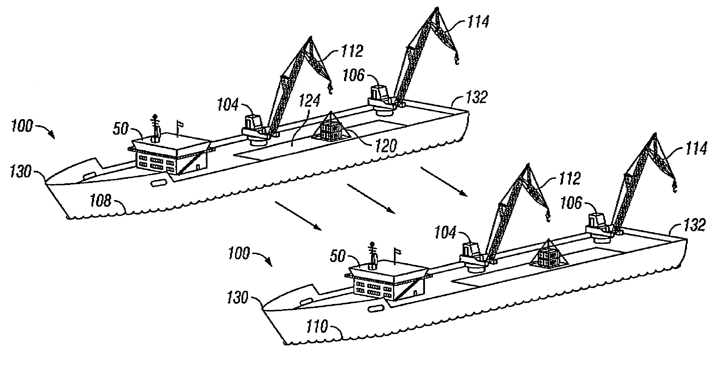
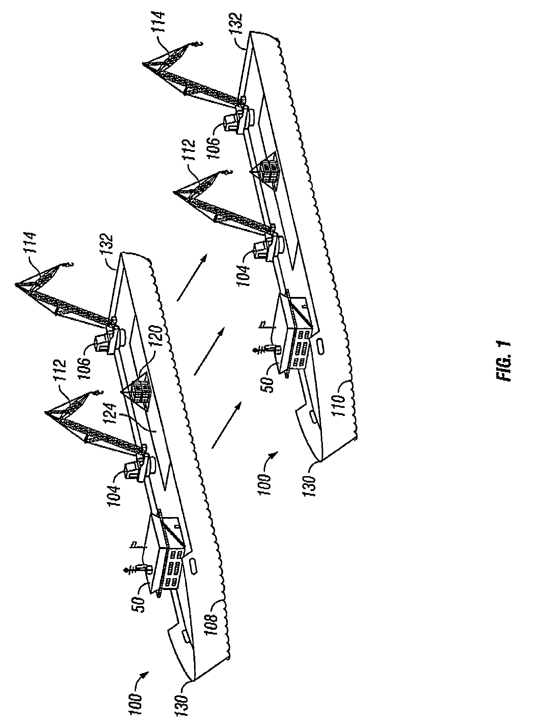
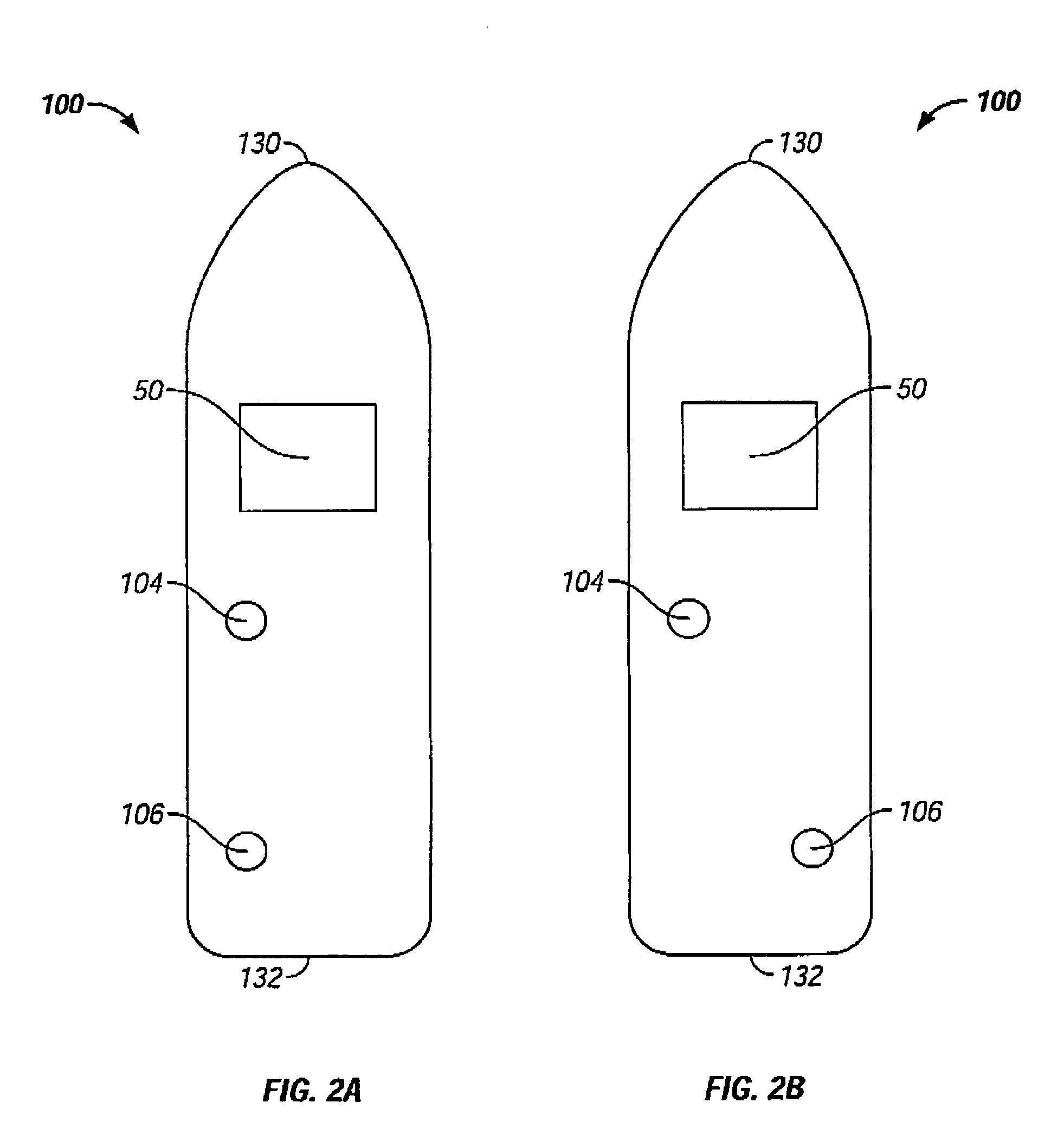
[0024]The present invention is a method for lifting and transporting a heavy load. The invention was developed to convert these heavy lifting ships into heavy transportation and installation vessels for use in the offshore sector. The preferred vessels are mono-hull transportation vessels, equipped with at least two heavy lift mast cranes.

[0025]The present invention is a method for lifting a load using a heavy lift ship equipped with modular units.

[0026]The fly-jib module is fitted to the existing crane jibs in order to extend outreach and lifting height of the crane. An example of the useful need of the fly-jib module is installing a topside construction onto floating production storage and offloading facilities (FPSO).

[0027]The suction anchor module when installed on the heavy l...


PUM


Abstract

The invention is a method for lifting and transporting a heavy load by using a heavy lift vessel with at least two heavy lift cranes adapted to operate simultaneously; mounting fly-jibs on the heavy lift crane to increase reach and height of the heavy lift crane; picking up a load from a first location using the fly-jib modules simultaneously; shifting the load from the first location to over a second location on the heavy lift vessel; placing the load on the second location; moving the heavy lift vessel to a second position; using a mooring system to maintain the heavy lift vessel at the second position; picking up the load from the second location using the fly-jib modules simultaneously; shifting the load from a second location to over a third location; and placing the load on the third location.

Description

FIELD OF THE INVENTION[0001]The invention relates to a method for lifting and transporting a heavy load using a heavy lift vessel with at least one heavy lift crane and fly-jib module mounted on the heavy lift cranes to increase reach and height of the heavy lift cranes.BACKGROUND OF THE INVENTION[0002]As global commerce has expanded, it has become increasingly necessary to effectively transport goods from one location to a remote location that transverses over water. Containers of goods are transported inland by means of railroads, trucks, inland waterway vessels, etc. The permissible range of operation of land-bound carriers or vessels for inland navigation ends at the coast. At that point, cargo transported by inland waterway vessels must be transferred from a non-seaworthy inland vessel to a seaworthy ship. Cargo must also be loaded from land locations to the seaworthy ships.[0003]Transportation problems compound and the risk of loss increases as the cargo becomes heavier, requi...

Claims


Application Information

Patent Timeline
Patent Type & Authority Patents(United States)
IPC IPC(8): B66D1/28B66D1/36B63B27/10B66C23/52B66C23/66
CPCB63B27/10B66C23/52B66C23/66
Inventor KRABBENDAM, RICHARD L.
Owner KRABBENDAM RICHARD L
Why Eureka
Try Eureka