
Apparatus for supporting a camera and method for using the apparatus

a technology for supporting apparatus and cameras, applied in the direction of optics, viewfinders, instruments, etc., can solve the problems of not knowing how to operate the camera, difficult to use such tripods, and inability to secure the foundations. to achieve the effect of convenient us

Active Publication Date: 2010-03-23
FROMM WORKS (US) INC
View PDF52 Cites 61 Cited by
  • Summary
  • Abstract
  • Description
  • Claims
  • Application Information

AI Technical Summary

Benefits of technology

[0013]It is an object of the present invention to provide an apparatus whereby the user of a camera can readily take an image of him or her self at any time alone or as part of a group, can readily take pictures when the view may be blocked as by a crowd, can readily be used by people confined to wheelchairs or the like, and can readily be used underwater by using the camera self-timer function or a camera remote control function, which camera overcomes the disadvantages of know prior art devices.
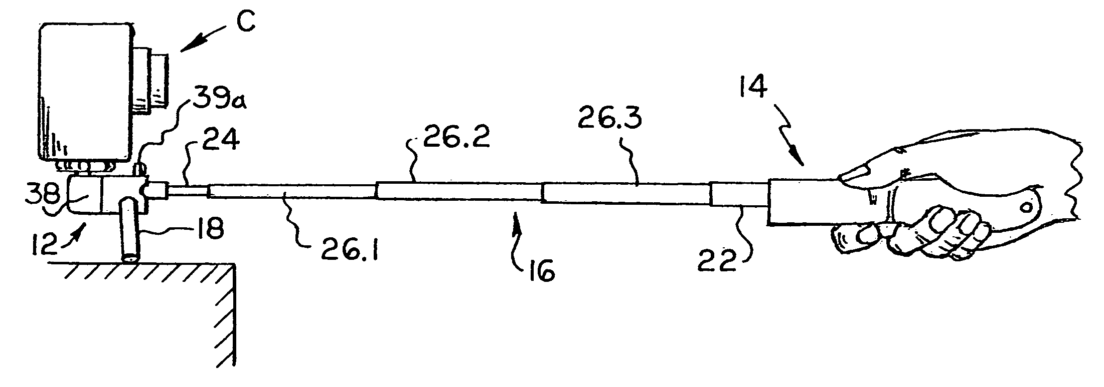
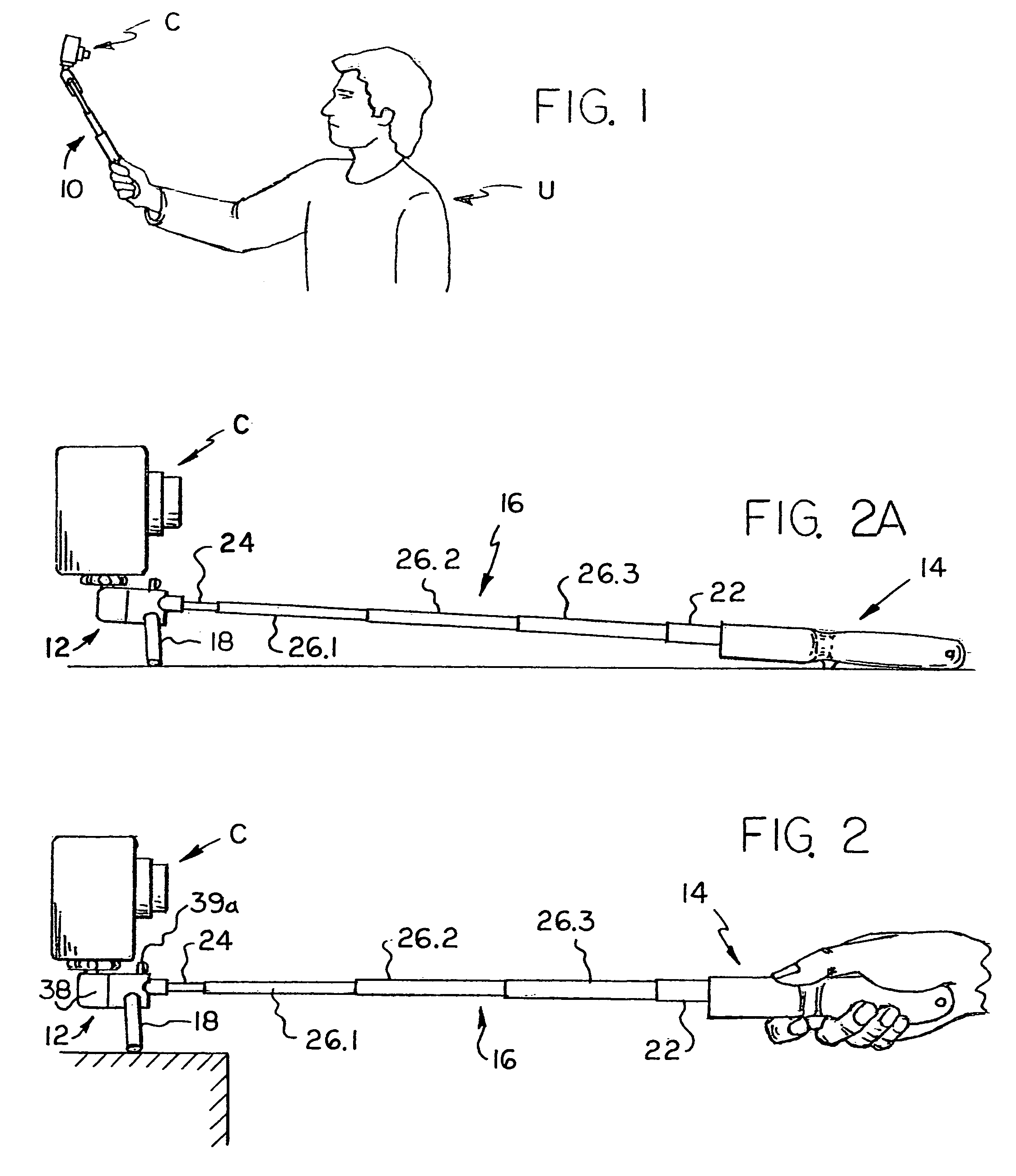
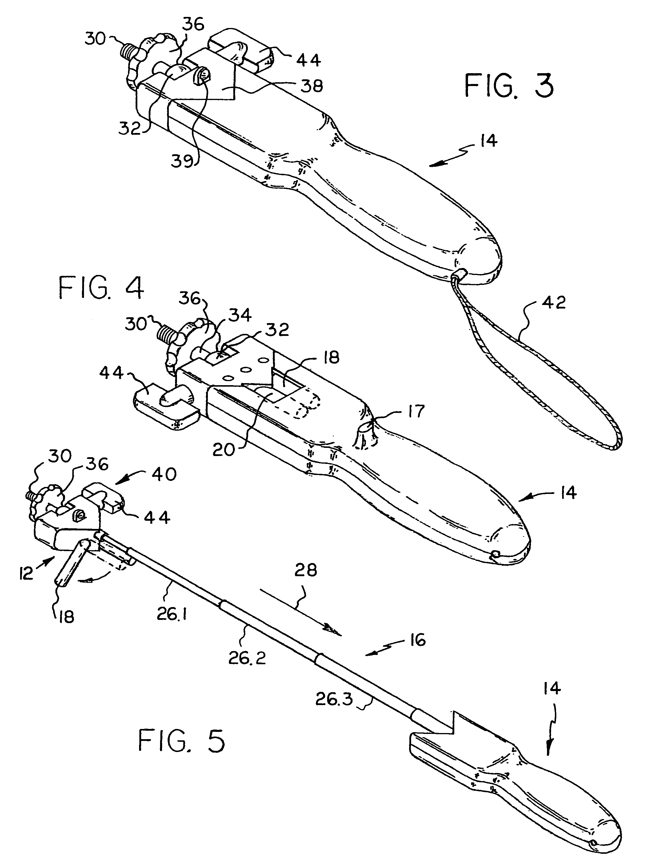
[0014]More particularly it is an object of the present invention to provide an apparatus for supporting a camera by hand, the apparatus including a base assembly which may be secured to a camera in various positions, a handgrip, and an elongated support which extends between the handgrip and the base assembly whereby the user of the camera may secure a camera to the base assembly and, either by setting the self-timer or by using a remote control device, and while holding the handgrip, position the camera a distance away, which may be greater than arms length, to capture a still or moving image of the user.
[0016]Yet another object of the present invention is to provide a hand held elongated camera support which may be used to explore by camera hard-to-reach or unsafe areas by using the self-timer function of the camera or a camera remote control device.
[0019]It is an additional object of the present invention to provide an extensible support with a motorized function so that a camera carried by the support can be moved towards and away from the user to, in effect, provide the camera with a zoom function.
[0020]Another object of the present invention is to provide a device for taking a picture when the view is blocked by a crowd; for example, a parade when a crowd is between the user and the parade.
[0023]The foregoing objects and other objects and advantages of this invention will be more fully understood after a consideration of the following detailed description taken in conjunction with the accompanying drawings. As can be seen from the following drawings, the apparatus of this invention includes a base assembly which may be secured to a camera, a handgrip, and an elongated support. The base assembly in the illustrated embodiments affixes to the bottom tripod mount on a camera, which camera may be provided with a self-timer, remote shutter release, or a remote control device. The user of the camera and the apparatus of the present invention will hold the handgrip and aim the camera with the lens facing himself. This allows self-portraits with an extended reach eliminating distortion, discomfort and overexposure due to the close proximity of the flash. The apparatus of this invention has the main feature of the “capture yourself” function, but the apparatus is multi-functional and may be used like a regular monopod, or in some embodiments, as a regular tripod. In addition, the apparatus may be used for taking pictures of scenes which would otherwise be obstructed. While many camcorders come with a self-timer function there are others that do not. While some camcorders come with a remote control device, others do not. Therefore, when using a camcorder without a remote control device, the user will initially hold the camera on the apparatus of this invention with one hand and depress the record button with the other hand. He (or she) will then suitably position the apparatus for recording his or her image, and then bring the camcorder back to the initial position so he or she can stop recording. It is a simple task to eliminate unwanted images during playback or edit mode on the camcorder or on a computer during an optional editing process.

Problems solved by technology

While these prior art tripods are suitable for their intended purposed, it is sometimes difficult to use such tripods.
For example, on a beach secure foundations are not readily available.
Strangers can be asked to photograph an individual or group, but they may not know how to operate the camera, or may operate it poorly.
Alternatively, they may run off and steal the camera.
The stranger may damage the camera with hands contaminated with sand, sea salt, and / or suntan lotion.
However, this is uncomfortable and may cause distortion due to the body position and camera angle.
Also, when the camera is held this way, the camera lens angle may not be sufficiently wide to include the camera user and anything else that he or she would like to be included in the picture.
However, as can be seen from FIGS. 2 and 3 of U.S. Pat. No. 4,530,580 if the telescoping arm was coupled directly to the camera the desired position of the camera may not be obtained as the camera can only be angled about the axis of the mounting stud.
In addition, if the use of a mirror was desired, the telescoping arm could only be used with the disc-7 camera.
Another disadvantage of the telescoping arm of the Minolta design was that it lacked detents or similar locking means to prevent unintentional retraction.
It is very difficult for a person in a wheelchair to set a camera on a tripod and move to a preferred position in the photo(s) before the self timer activates.
Sometimes the user of a camera would like to take pictures underwater, however, even though most waterproof cameras are provided with a tripod mount, it is difficult to set-up a tripod underwater.
In addition, the user of a camera may want to explore by camera hard-to-reach or unsafe areas.

Method used


Image

  • Apparatus for supporting a camera and method for using the apparatus
  • Apparatus for supporting a camera and method for using the apparatus
  • Apparatus for supporting a camera and method for using the apparatus

Examples


second embodiment

[0057]this invention is illustrated in FIGS. 8-9. In this embodiment there are no tripod legs, and the elongated support 16 may be motorized to cause it to be moved between retracted and extended positions. A camera “C” may be mounted on the base assembly 12. By simply using the rocker switch 29 to operate the motorized extensible and retractable support, the camera can be moved towards and away from the user. This is particularly useful when using camcorders, such as the one illustrated in FIG. 10 at “VC”, to give a zoom effect. Thus, the user “U” of the camera, can point it at himself, and by working the rocker switch 29 zoom in and out. If the camera is provided with a swivel LCD, the motorized function can also be used to crop the image before it is taken.

[0058]Motorized mechanisms for moving parts towards and away from each other are well known and are therefore not illustrated. One example is the mechanisms used for zoom lenses in cameras. In this embodiment the elongated supp...

third embodiment

[0060]With further reference to the third embodiment shown in FIG. 10, this embodiment is provided with a D-shaped handgrip. The handgrip is in the shape of a D-shaped handle to provide greater support for the user, which type of handle will offer better support if the camera / camcorder is on the heavy side, and may also prevent horizontal slippage. If the apparatus of FIG. 10 does not have a motorized function, and if the video camera is provided with a remote control device “RC”, the user may use the remote control device to achieve a zoom function. In this regard, it should be noted that the camera illustrated is provided with a swivel LCD view screen, which may be positioned so the user can see it.

[0061]While an extensible support has been described which is either motorized or telescoping, other forms of extensible supports may be utilized. For example, as shown in FIG. 11, a rack 70 and pinion 72 design may be employed, the pinion being operated by a knurled wheel 74. This desi...

embodiment 10

[0071]FIG. 22 shows an embodiment 10 without the removable pocket clip, but showing a wrist strap 42 or lanyard secured to a lanyard clip 90 carried by the hand portion 14. Also shown is a mounting sleeve 51 which may be carried by any suitable mounting platform or structure, such as for example the round disk 53. If desired, the embodiment shown in FIG. 22 can be slipped into the sleeve in the manner shown.

[0072]Finally, FIG. 23 shows how two camera supports 10 of this invention may be secured to each other to extend the reach of the apparatus. While the left hand apparatus 10 is shown in its retracted position, it should be obvious that it may be extended.


PUM


Abstract

A camera support assembly including an elongated support, such as a extensible support, which support extends between a base assembly and a handgrip, whereby a user of the camera may secure a camera to the base assembly and, while holding the handgrip, position the camera a distance away, which may be greater than arms length, to capture a still or moving image of the user, of an obstructed scene, or of hard to reach and / or unsafe areas.

Description

CROSS-REFERENCE TO RELATED APPLICATIONS[0001]This application is a continuation-in-part of U.S. application Ser. Nos. 11 / 125,693 and 11 / 227,652, filed May 10, 2005 and Sep. 15, 2005, respectively, now abandoned, and also claims priority from European patent application Ser. No. 06 009 443.0 filed May 8, 2006.TECHNICAL FIELD[0002]The present invention relates generally to camera supports and methods of using, and more particularly to an assembly including an elongated support, which is preferably an extensible support, such as a telescoping support, which support extends between a base assembly and a handgrip, whereby a user of the camera may secure a camera to the base assembly and, after setting the self-timer on the camera or by using a remote control, position the camera a distance away while holding the handgrip, which distance may be greater than arms length, to capture a still or moving image of the user, or to capture an event blocked by a crowd or the like, or to explore har...

Claims


Application Information

Patent Timeline
Patent Type & Authority Patents(United States)
IPC IPC(8): G03B13/02
CPCF16M11/14F16M11/18F16M11/28F16M13/04G03B17/56F16M2200/022G03B17/561G03B17/563
Inventor FROMM, WAYNE G.
Owner FROMM WORKS (US) INC
Learn More