Apparatus for supporting a camera and method for using the apparatus
a technology for supporting apparatus and cameras, applied in the direction of viewfinders, instruments, optics, etc., can solve the problems of difficult use of tripods, inability to know how to operate cameras, and inability to secure the foundations. to achieve the effect of reducing distortion, discomfort and overexposur
- Summary
- Abstract
- Description
- Claims
- Application Information
AI Technical Summary
Benefits of technology
Problems solved by technology
Method used
Image
Examples
second embodiment
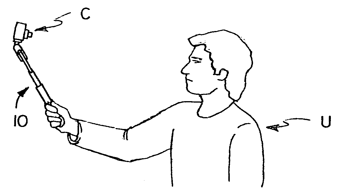
[0052] this invention is illustrated in FIGS. 8-9. In this embodiment there are no tripod legs, and the elongated support 16 may be motorized to cause it to be moved between retracted and extended positions. A camera “C” may be mounted on the base assembly 12. By simply using the rocker switch 29 to operate the motorized extensible and retractable support, the camera can be moved towards and away from the user. This is particularly useful when using camcorders, such as the one illustrated in FIG. 10 at “VC”, to give a zoom effect. Thus, the user “U” of the camera, can point it at himself, and by working the rocker switch 29 zoom in and out. If the camera is provided with a swivel LCD, the motorized function can also be used to crop the image before it is taken.
[0053] Motorized mechanisms for moving parts towards and away from each other are well known and are therefore not illustrated. One example is the mechanisms used for zoom lenses in cameras. In this embodiment the elongated su...
third embodiment
[0055] With further reference to the third embodiment shown in FIG. 10, this embodiment is provided with a D-shaped handgrip. The handgrip is in the shape of a D-shaped handle to provide greater support for the user, which type of handle will offer better support if the camera / camcorder is on the heavy side, and may also prevent horizontal slippage. If the apparatus of FIG. 10 does not have a motorized function, and if the video camera is provided with a remote control device “RC”, the user may use the remote control device to achieve a zoom function. In this regard, it should be noted that the camera illustrated is provided with a swivel LCD view screen, which may be positioned so the user can see it.
[0056] While an extensible support has been described which is either motorized or telescoping, other forms of extensible supports may be utilized. For example, as shown in FIG. 11, a rack 70 and pinion 72 design may be employed, the pinion being operated by a knurled wheel 74. This de...
embodiment 10
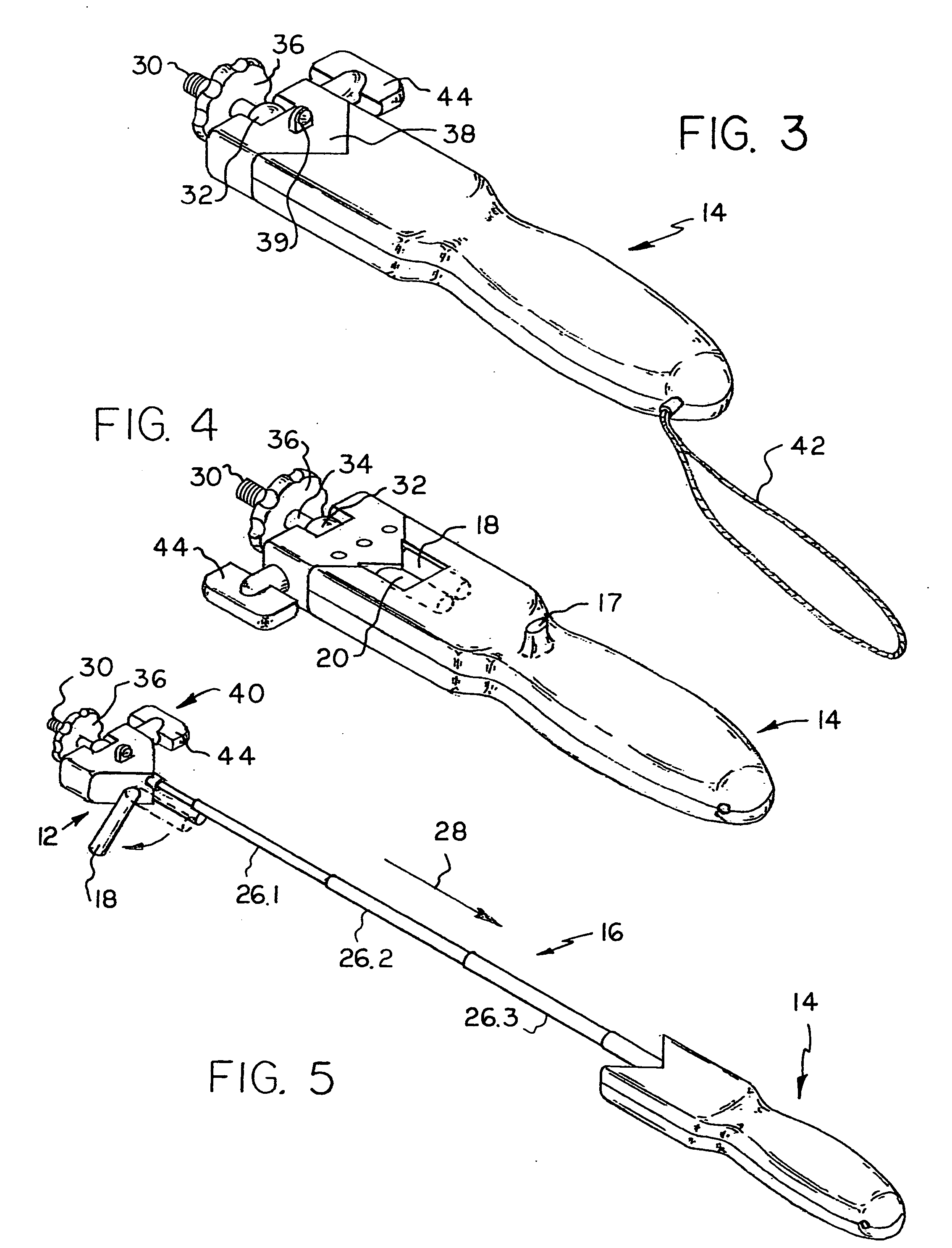
[0066]FIG. 22 shows an embodiment 10 without the removable pocket clip, but showing a wrist strap 42 or lanyard secured to a lanyard clip 90 carried by the hand portion 14. Also shown is a mounting sleeve 51 which may be carried by any suitable mounting platform or structure, such as for example the round disk 53. If desired, the embodiment shown in FIG. 22 can be slipped into the sleeve in the manner shown.
[0067] Finally, FIG. 23 shows how two camera supports 10 of this invention may be secured to each other to extend the reach of the apparatus. While the left hand apparatus 10 is shown in its retracted position, it should be obvious that it may be extended.
PUM
 Abstract
Description
Claims
Application Information
 - R&D
- Intellectual Property
- Life Sciences
- Materials
- Tech Scout
- Unparalleled Data Quality
- Higher Quality Content
- 60% Fewer Hallucinations
Browse by: Latest US Patents, China's latest patents, Technical Efficacy Thesaurus, Application Domain, Technology Topic, Popular Technical Reports.
© 2025 PatSnap. All rights reserved.Legal|Privacy policy|Modern Slavery Act Transparency Statement|Sitemap|About US| Contact US: help@patsnap.com


