Extended reach ultrasonic toothbrush with improvements

a technology of ultrasonic toothbrushes and extension reach, which is applied in the field of ultrasonic toothbrushes, can solve the problems of reducing the efficiency of the ultrasonic wave emitted by the transducer, not providing the ultimate performance, and not generating or transmitting ultrasonic energy to the teeth and gums, and achieves a high-efficiency ultrasonic, prolongs the reach of ultrasonic waves, and minimizes the attenuation of the ultrasonic wave between

Inactive Publication Date: 2009-08-27
ROBERT T BOCK CONSULTANCY
View PDF3 Cites 62 Cited by
  • Summary
  • Abstract
  • Description
  • Claims
  • Application Information

AI Technical Summary

Benefits of technology

[0012]Responding to the above-described unresolved needs, this invention provides a highly efficient ultrasonic toothbrush, wherein the attenuation of the ultrasonic waves between the transducer and the oral cavity is minimized, extending the reach of the ultrasonic waves by providing the highest possible level of ultrasonic output from the brush head.
[0013]The ultrasonic toothbrush typically comprises a handle portion and a head portion. The handle portion houses a rechargeable battery, an electric motor to generate sonic frequency physical vibration of the head portion through a motion transducer, and an electronic system to provide operational control of the toothbrush. The electronic system typically has an on-off switch, battery charge control, speed control for the motor and generates the ultrasonic frequency electrical current to power the ultrasonic transducer. The head portion of the toothbrush houses the bristle tufts and an ultrasonic transducer, which protrudes from the head portion of the toothbrush.
[0014]The protruding and exposed ultrasonic transducer positioned in close proximity to the tips of bristle tufts is the key inventive step in this generation of the ultrasonic toothbrush design. The invention eliminates all of the attenuating surface interfaces of the previous state of art of U.S. Pat. Nos. 5,138,733 and 5,247,716 namely the transducer to the inside surface of the housing, the outside surface of the housing to the inside surface of the brush head, and the brush head to bristle interface. Not using the bristles as the ultrasound transmitting media eliminates the attenuation of the ultrasound by the bristles. The invention is also superior to the acoustic waveguide design shown in U.S. Pat. No. 7,269,873 B2, as explained in the prior art section of the specifications. The current invention eliminates all attenuation of ultrasound energy by placing the ultrasound transducer in direct contact with the mixture of the saliva and the dentifrice in close proximity with the tips of the bristles, wherein this non-attenuated ultrasound energy in combination with the optionally vibrating bristle tufts create mild cavitation and acoustic streaming within the fluids in the oral cavity, enhancing the plaque removing action of the bristles. The invention eliminates the attenuation of the ultrasound energy emitted by the piezoelectric transducer by eliminating all surface interfaces, bristles, and acoustic waveguides of the prior art.

Problems solved by technology

The physical vibration of the bristles enhances plaque removal and provides a pleasant feeling and instant feedback to the user, but still does not generate or transmit ultrasonic energy to the teeth and gums.
Due to these two attenuating mechanisms the ultrasonic waves emitted by the transducer are reduced in efficiency and still does not provide the ultimate performance.
In addition, the mechanism of U.S. Pat. No. 7,269,873 became much more complex and more expensive than the one invented by Bock in U.S. Pat. No. 5,138,733.
What has occurred to date is that not withstanding the teachings of the prior art, the ability to provide ultrasonic wave transmission effectively, inexpensively, and easily has remained unsolved.

Method used


Image

  • Extended reach ultrasonic toothbrush with improvements
  • Extended reach ultrasonic toothbrush with improvements
  • Extended reach ultrasonic toothbrush with improvements

Examples


Embodiment Construction

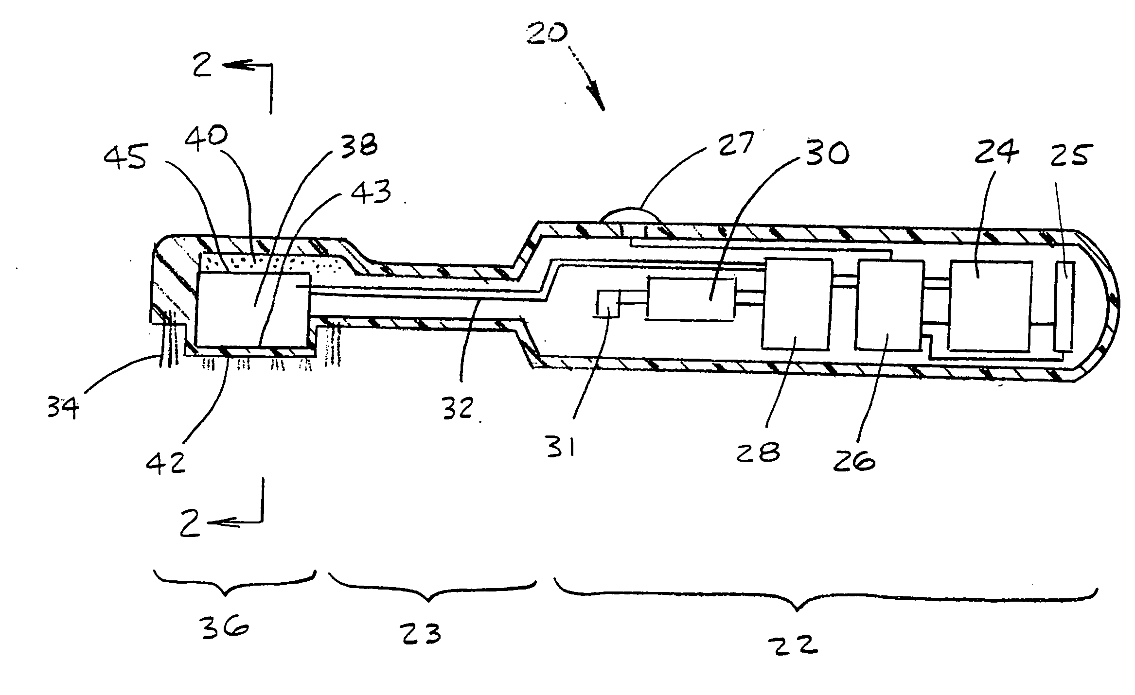
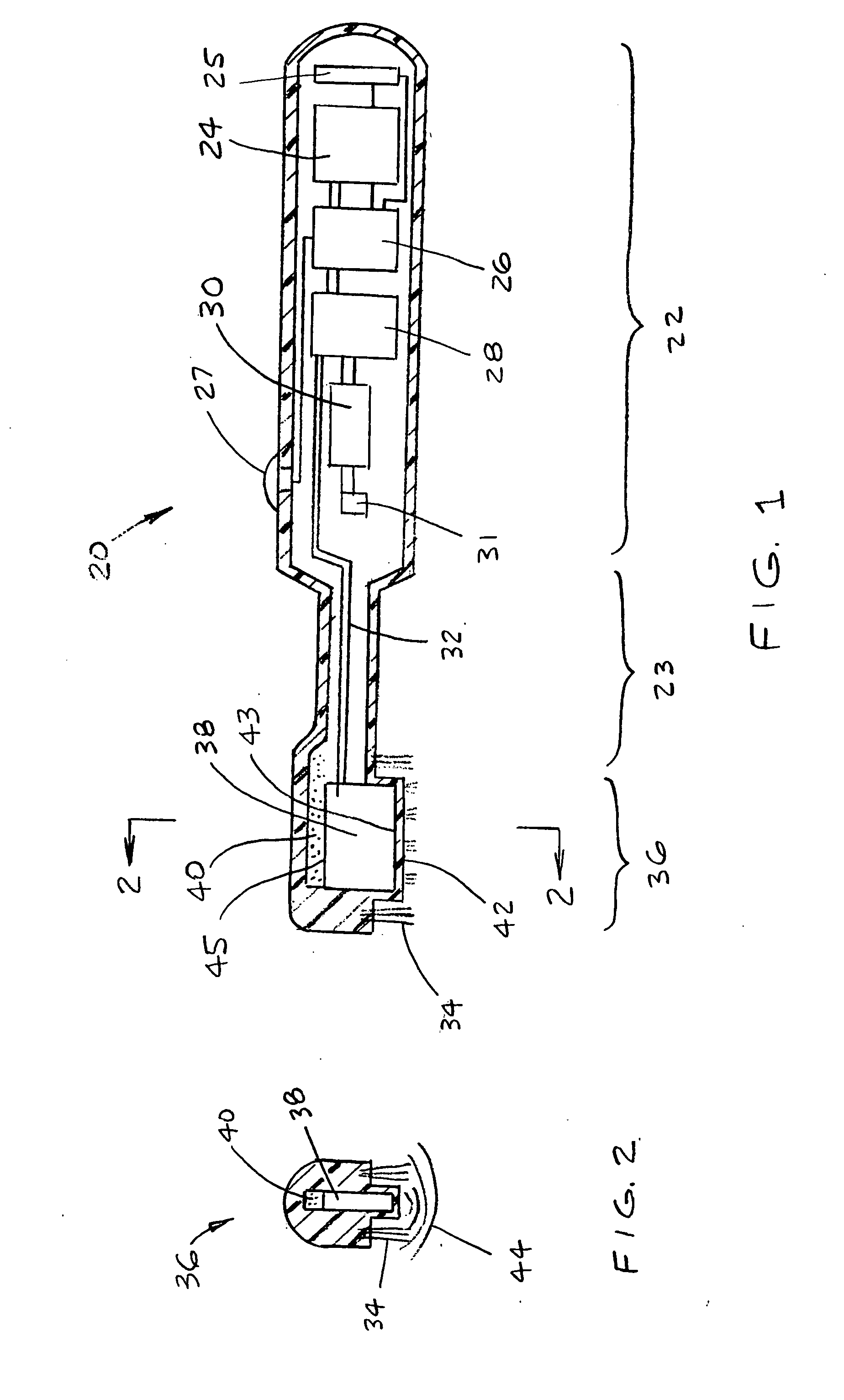
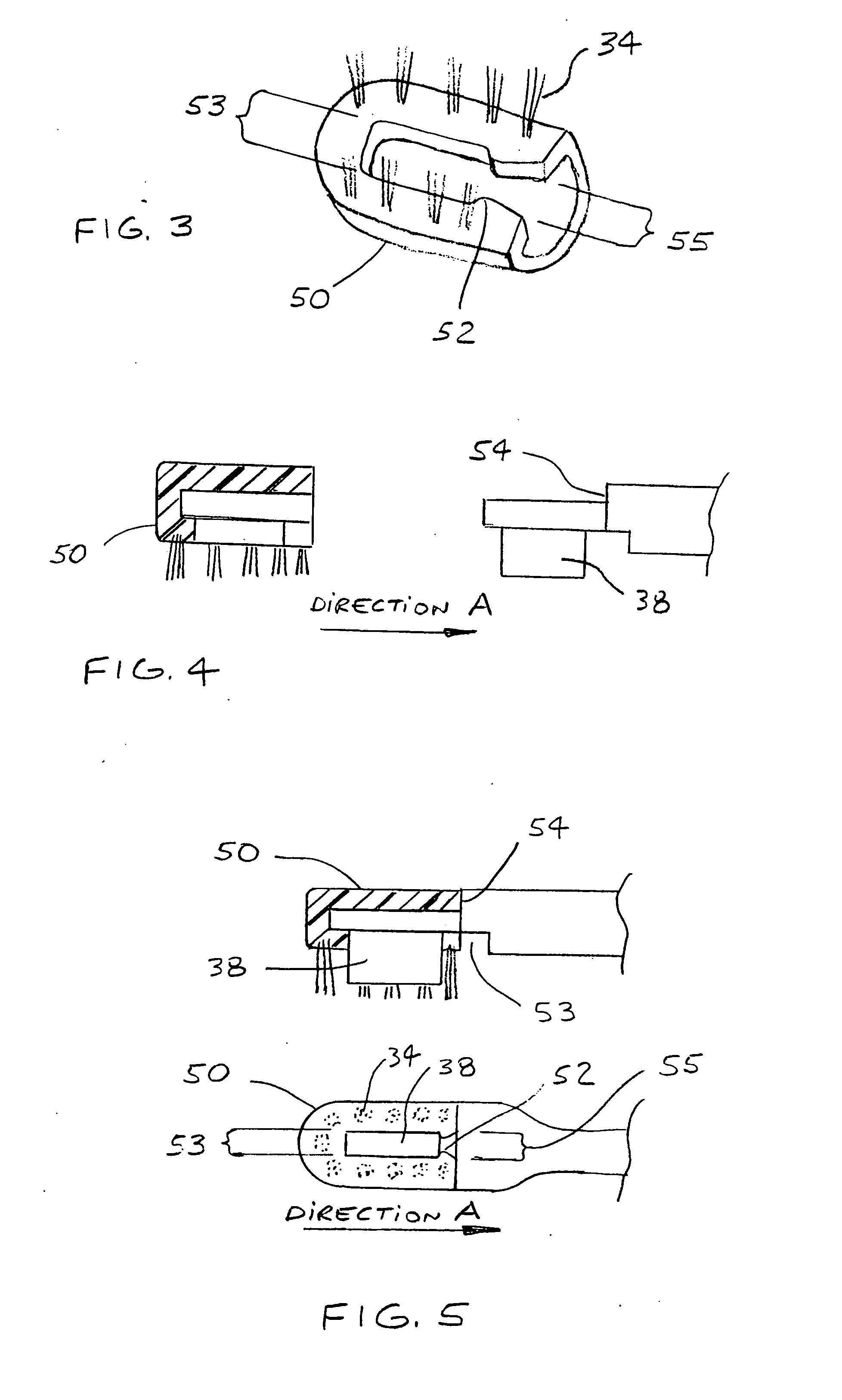
[0024]Description of the Basic Device.

[0025]Referring in detail to the drawings, the reference numerals herein refer to the like numbered parts in the drawings. In the following discussion, unless otherwise qualified, the term “ultrasound” refers to acoustic energy in either continuous wave ultrasound or a repetitive burst type ultrasonic modality, having a frequency higher than 20 kHz. When reference is made to “sonic” or “sonic vibrations”, unless otherwise qualified, it is a reference to a vibrating or oscillating motion below 20 kHz frequency. The term “cavitation” in association with the ultrasonic toothbrush refers to the generation, activation, or bursting of bubbles in the fluids in the oral cavity. The reference to “fluids in the oral cavity”, unless otherwise qualified, is typically a mixture of saliva, water and dentifrice. “Acoustic streaming” refers to a flow of fluids driven by an acoustic wave emitted by the ultrasonic transducer. When reference is made to “ultrasound...


PUM


Abstract

An ultrasonic toothbrush for daily oral hygiene application is disclosed, having an ultrasound transducer in direct contact with the fluids in the oral cavity, without ultrasound energy attenuation between the transducer and the fluids in the oral cavity. Maximum level of ultrasound energy coupled to the fluids within the oral cavity and to the teeth and gums and periodontal pockets, achieving maximum loosening of soft plaque. Toothbrush configurations of ultrasonically enhanced manually operated toothbrushes and motorized toothbrushes having lateral direction sonic frequency vibrating brush heads emitting ultrasonic energy are disclosed. To generate the sonic frequency lateral vibration of the brush head, a motion transducer is utilized. Removable and user replaceable brush heads are described. In the various configurations low voltage DC energy supplied by a battery is converted to ultrasonic frequency DC current to activate the ultrasonic transducer. All configurations are utilizing bristle tufts to effectively dislodge plaque loosened by the ultrasonic waves from the surfaces of teeth and gums.

Description

RELATED APPLICATION[0001]This application is a continuation-in-part of U.S. patent application Ser. No. 12 / 072,228 filed Feb. 25, 2008 entitled Extended Reach Ultrasonic Toothbrush.BACKGROUND[0002]1. Field of Invention[0003]This invention relates to ultrasonic toothbrushes. More particularly the invention is concerned with improving the efficiency of earlier generation ultrasonic toothbrushes, improving the coupling of the ultrasonic energy to the fluids in the oral cavity, and the teeth and gums of the user.[0004]2. Description of Prior Art[0005]Powered toothbrushes introduced in the 1950 period provided an improvement over manual toothbrushes, particularly so for individuals with limited dexterity.[0006]Numerous unsuccessful attempts were made and disclosed by U.S. Pat. No. 3,335,443 by Parisi, U.S. Pat. No. 3,809,977 by Balamuth et. al., U.S. Pat. No. 4,192,035 by Kuris, and others to develop improved powered toothbrushes by attempting to vibrate the brush head or the bristles by...

Claims


Application Information

Patent Timeline
Patent Type & Authority Applications(United States)
IPC IPC(8): A46B13/00A46B9/04A61C1/07A61H7/00
CPCA46B13/023A46B15/0002A46B2200/1066A61H13/00A61C17/22A61C17/222A61C17/3436A61C17/20
Inventor BOCK, ROBERT T.
Owner ROBERT T BOCK CONSULTANCY
Why Eureka
Try Eureka