Light guide-based luminaire

a technology of luminaires and guides, applied in the field of luminaires, to achieve the effects of reducing light loss, reducing glare, and increasing the optical efficiency of luminaires

Active Publication Date: 2022-04-05
SIGNIFY HLDG BV
View PDF7 Cites 1 Cited by
  • Summary
  • Abstract
  • Description
  • Claims
  • Application Information

AI Technical Summary

Benefits of technology

[0009]In accordance with embodiments of the present invention, a photo frame-style frame is provided around the edge of the optical stack of a luminaire, and in which the optical stack is made of materials that are transparent to radio waves such that at least a central area of the optical stack that is delimited by the frame, i.e. the conduit, is transparent to such radio waves. Consequently, a module including at least one component for generating or receiving said radio waves such as a wireless receiver for receiving control signals of the light source(s) may be placed behind the optical stack, i.e. facing its further surface, as the radio frequency (RF) signals to be received by the wireless receiver can travel through this central region of the optical stack. This improves the appearance of the luminaire as the module no longer needs to be provided in front of the optical stack in order to be able to receive such RF signals, and allows the frame to be slimmer than for example the frame disclosed in CN 105 065 990 A due to the fact that at least the wireless receiver no longer needs to be integrated in the frame. This also allows for the frame to be made of metal, which may be aesthetically preferable, which is problematic in this prior art as such a metal frame can stop the RF signals from reaching the wireless receiver in the frame.
[0012]The at least one light source preferably comprises a plurality of solid state lighting elements arranged along one or more edge surfaces of the optical stack. The optical stack may further comprise a planar diffuser on the first major surface or the light guide in order to further diffuse the luminous output of the light guide, e.g. to further homogenize the luminous output of the light guide and / or to reduce glare. The optical stack may further comprise a planar reflector on the second major surface or the light guide in order to increase the optical efficiency of the luminaire by reducing light losses through the further surface of the optical stack.
[0013]The frame may comprise a plurality of frame elements cooperating to form the frame, at least some of said frame elements comprising an elongate surface facing one of said edge surfaces, wherein at least some of the light sources are mounted on said elongate surface in order to allow light to be coupled into the light guide. For example, the light sources may be solid state elements carried by an adhesive strip adhered to the elongate surface. This is a particularly cost-effective manner of affixing the light sources to such an elongate surface because of the low manufacturing cost of the adhesive strip and the straightforward assembly of the luminaire.
[0014]Each frame element may comprise a U-shaped profile in which the optical stack is secured, as this facilitates a straightforward manner of securing the optical stack in the frame elements.

Problems solved by technology

This also allows for the frame to be made of metal, which may be aesthetically preferable, which is problematic in this prior art as such a metal frame can stop the RF signals from reaching the wireless receiver in the frame.

Method used


Image

  • Light guide-based luminaire
  • Light guide-based luminaire
  • Light guide-based luminaire

Examples


Embodiment Construction

[0024]It should be understood that the Figures are merely schematic and are not drawn to scale. It should also be understood that the same reference numerals are used throughout the Figures to indicate the same or similar parts.

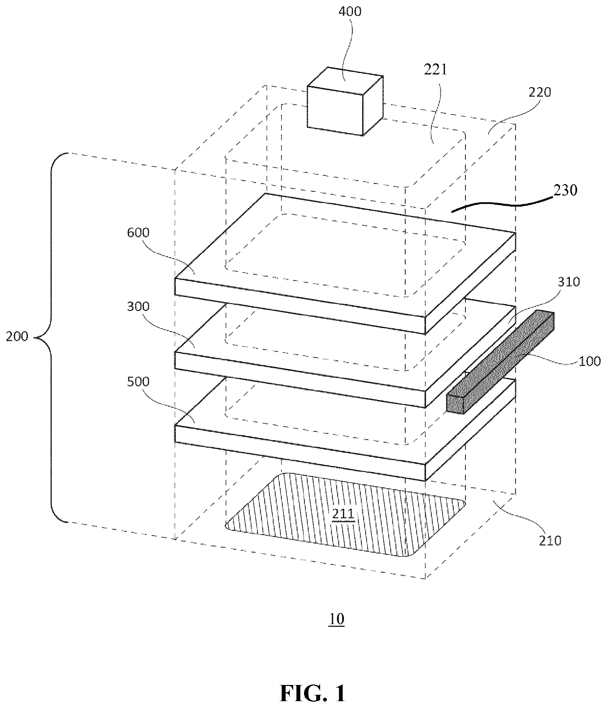
[0025]FIG. 1 schematically depicts an exploded view of part of a luminaire 10 according to embodiments of the present invention. The luminaire 10 comprises an optical stack 200 comprising at least a planar light guide 300 having opposing major surfaces between which one or more edge surfaces 310 extend. For example, in case of a circular light guide 300 the light guide would have a single edge surface 310, whereas in case of a polygonal light guide 300 the light guide would have a plurality of edge surfaces 310 matching the number of sides of the polygon, e.g. four edge surfaces 310 in case of a rectangular light guide 300 as schematically depicted in FIG. 1. It is noted for the avoidance of doubt that embodiments of the present invention are not limited to a...


PUM


Abstract

A luminaire is disclosed comprising an optical stack (200) transparent to radio waves, the optical stack comprising a first surface (210) including a light exit window (211) and a further surface (220) opposing the first surface, the optical stack including a planar light guide (300) having a first major surface facing or defining the first surface, an opposing second major surface facing or defining the further surface and at least one edge surface (310) extending between said opposing first and second major surfaces; and a frame (700) around the optical stack, the frame carrying at least one light source (100) optically coupled to one or more of said edge surfaces of the light guide, wherein the frame delimits the light exit window and an exposed portion (221) of the further surface opposing the light exit window, said light exit window and the exposed portion delimiting a conduit (230) for said radio waves through the optical stack.

Description

CROSS-REFERENCE TO PRIOR APPLICATIONS[0001]This application is the U.S. National Phase application under 35 U.S.C. § 371 of International Application No. PCT / EP2018 / 065165, filed on Jun. 8, 2018, which claims the benefit of European Patent Application No. 17176857.5, filed on Jun. 20, 2017. These applications are hereby incorporated by reference herein.FIELD OF THE INVENTION[0002]The present invention relates to a luminaire comprising an optical stack having a light exit surface and a further surface opposing the light exit surface, the optical stack comprising a planar light guide having a first major surface facing or defining the light exit surface, an opposing second major surface facing or defining the further surface and a plurality of edge surfaces extending between said opposing first and second major surfaces.BACKGROUND OF THE INVENTION[0003]With the advent of solid state lighting (SSL), e.g. LEDs, light guide-based luminaires have become increasingly commonplace. The light...

Claims


Application Information

Patent Timeline
Patent Type & Authority Patents(United States)
IPC IPC(8): F21V8/00H04B10/50H04B10/60
CPCG02B6/0088G02B6/0051G02B6/0055G02B6/0065H04B10/50H04B10/60F21V23/0435G02B6/0083F21V23/045F21Y2105/10F21K9/61G02B6/0095G02B6/0091
Inventor NIJKAMP, RICK GERHARDUSKETTELARIJ, HENDRIK JANGIELEN, VINCENT STEFAN DAVID
Owner SIGNIFY HLDG BV
Why Eureka
Try Eureka