Self-preserved amphibious landing of space hardware

a space hardware and amphibious technology, applied in the field of amphibious landing hardware recovery, can solve the problems of high cost of launch vehicles, inability to realize anticipated savings from reuse, and increased costs of additional systems, including propellant and guidance hardware, so as to slow down the first section and reduce weight

Active Publication Date: 2022-04-19
UNITED LAUNCH ALLIANCE
View PDF9 Cites 0 Cited by
  • Summary
  • Abstract
  • Description
  • Claims
  • Application Information

AI Technical Summary

Benefits of technology

[0006]The main engine of a launch vehicle is expensive and is capable of reuse if it can be economically recovered without damage. According to aspects of the present disclosure, a system and method for recovery and reuse of the main engine(s) of a launch vehicle is disclosed. More specifically, one or more parachutes are deployed to decelerate the decent of the first stage and main engine following separation from the second or upper stage. Appropriately sized parachutes and / or parafoils may be used to support the weight of the engine (approximately 18,000 lbs. in one embodiment) and the first stage structure (approximately 45,000 lbs. in one embodiment). At a predetermined altitude, the first section is purposefully severed into two sections. The first section includes the main engine and a portion of at least one propellant tank. The portion of the remaining propellant tank includes a central section of the tank and one closed end. The opposite closed end is severed as part of the process of severing the first stage into two sections. The second section includes a remaining portion of the at least one propellant tank and the opposite end of the first stage. The first section is connected to the parachute system. The second section is allowed to crash into the earth at a safe location. Severing the first stage reduces weight, which assists in slowing the descent of the first section, and also reconfigures the first section for a controlled splash down in a body of water.
[0007]Also, at a predetermined altitude or at a predetermined time, a second set of controlled explosions form a series of holes in the fuselage of the first section of the first stage. The holes extend through the wall of the remaining portion of the propellant tank. The second set of explosions may occur following or simultaneous with the first set of explosions that severs the first stage into two sections. The holes play a role in the deceleration of the first section at splash down and the stability and orientation of the first section in the water following splash down. Prior to splash down, the first section is oriented generally vertically with the engine farthest from earth and the open end of the severed open end of the first section closest to earth. Similarly, the remaining portion of the at least one propellant tank is vertically oriented with its closed end located proximate the engine and its severed open end facing the water. Upon splash down, the air within the propellant tanks acts as an air spring, allowing for gradual displacement of the water below the vehicle and pressure buildup within the tank. As water flows into the open end of the propellant tank, air is forced out of the propellant tank through the side holes. Once the water flowing into the tank reaches the level of the side holes, the flow of water into the tank is stopped, and the remaining tank volume above the vented plane acts as a buoyance element.
[0008]In addition, and prior to splash down, one or more buoyancy devices are deployed at positions surrounding the main engine. The buoyancy devices may be air filled devices. The buoyancy devices also decelerate the first section upon splash down and maintain the first section afloat following splash down. Also, the water filled portion of the propellant tank acts to stabilize the orientation of the first section with the engine out of the water.

Problems solved by technology

Launch vehicles are expensive.
Unfortunately, the anticipated savings from reuse did not materialize.
While savings are expected from the ability to reuse the first stage, there are added expenses in the cost of the additional systems, including propellant and guidance hardware, that must be carried into space as part of the initial launch in order to be able to recover the first stage for subsequent uses.

Method used


Image

  • Self-preserved amphibious landing of space hardware
  • Self-preserved amphibious landing of space hardware
  • Self-preserved amphibious landing of space hardware

Examples


Embodiment Construction

[0029]Those of skill in the art will recognize that the following description is merely illustrative of the principles of the invention, which may be applied in various ways to provide many different alternative embodiments. This description is made for illustrating the general principles of the teachings of this invention and is not meant to limit the inventive concepts disclosed herein. The detailed description is to be construed as exemplary only and does not describe every possible embodiment since describing every possible embodiment would be impractical, if not impossible. Numerous alternative embodiments could be implemented, using either current technology or technology developed after the filing date of this patent, which would still fall within the scope of the claims.

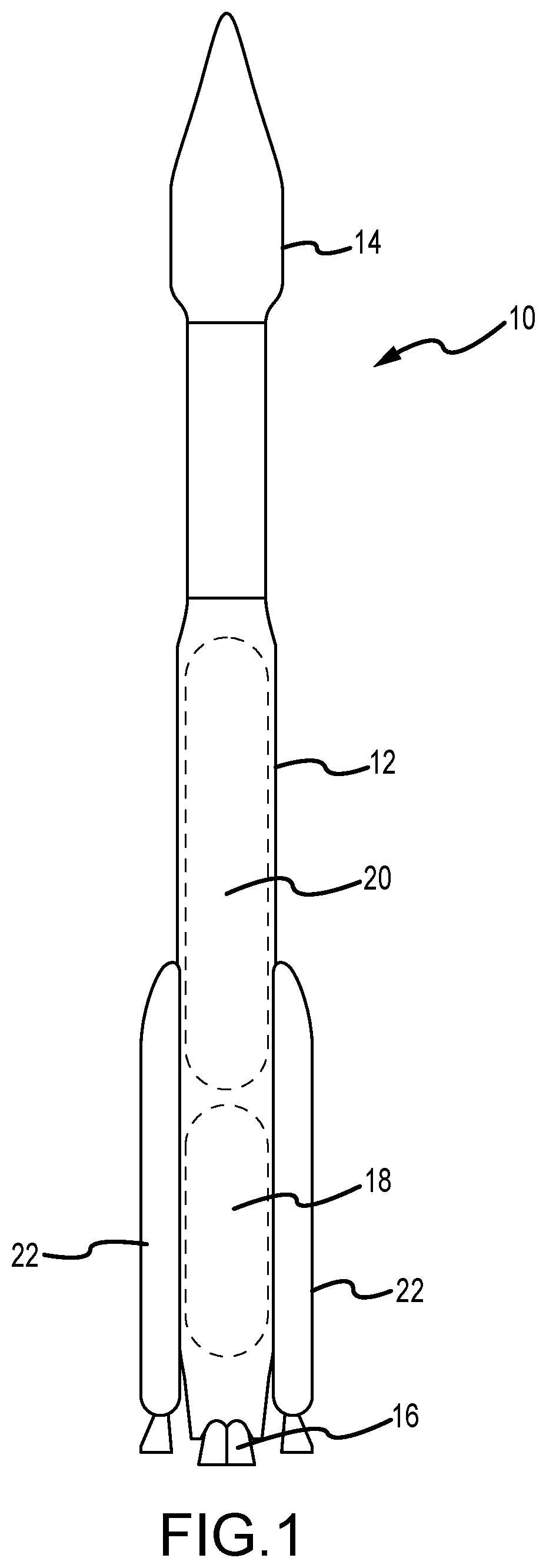
[0030]Turning to FIG. 1, an exemplary launch vehicle 10 is illustrated. The launch vehicle has a first stage 12 and a second stage 14. The main engine 16 is located at the bottom of the first stage 12 as the ...


PUM


Abstract

A method for preserving and recovering the main engine of the first stage of a multistage launch vehicle involves utilizing a portion of a first stage propellant tank together with a parachute and a deployed buoyancy device to float the engine in a body of water until the engine can be recovered. Controlled explosions remove portions of the propellant tank to permit it to stabilize the position of the engine relative to the water following splash down.

Description

CROSS-REFERENCE TO RELATED APPLICATIONS[0001]This application is a continuation and claims the benefit of U.S. patent application Ser. No. 15 / 918,078 filed Mar. 12, 2018 (now issued U.S. Pat. No. 10,569,908), which claims the benefit of U.S. Provisional Patent Application Ser. No. 62 / 633,398, filed Feb. 21, 2018, the entirety of both is incorporated herein by reference.FIELD OF THE INVENTION[0002]Embodiments of the present disclosure generally relate to hardware, systems and methods for amphibious recovery of launch vehicle hardware. More specifically, embodiments of the present disclosure address the recovery of first stage hardware, including main engines and booster engines.BACKGROUND OF THE INVENTION[0003]Launch vehicles are expensive. Recovery and reuse of spacecraft and launch vehicles has been an objective for decades. However, the economics of spacecraft and launch vehicle recovery are significant and daunting. NASA's space shuttle is regarded as the first recoverable and re...

Claims


Application Information

Patent Timeline
Patent Type & Authority Patents(United States)
IPC IPC(8): B64G1/00B64G1/62
CPCB64G1/002B64G1/62B64G1/401B64G1/402
Inventor COYNE, BRENDAN M.LAMPARIELLO, JAMESWEHRWEIN, DANIEL A.
Owner UNITED LAUNCH ALLIANCE
Why Eureka
Try Eureka