Ball lift sleeve and retrieval tool for oil and gas wells

a technology sleeves, which is applied in the field of ball sleeves and retrieval tools for oil and gas wells, and can solve the problems of extreme damage and hazards, the type of plungers was even challenging, and the use of pump jacks is much more expensiv

Active Publication Date: 2021-02-11
ELK N LIZARD LLC
View PDF0 Cites 0 Cited by
  • Summary
  • Abstract
  • Description
  • Claims
  • Application Information

AI Technical Summary

Problems solved by technology

This type of plunger was even challenging the use of pumping units, pump jacks.
These pump jacks are much more expensive artificial lift systems used to handle these conditions.
The problems encountered by the plungers contained in the prior are, including, but not limited to: 1) the impurities in gas and liquid production are present and have to be addressed; 2) various flow rates and velocities are in encountered over production days requiring plunger adjustments (opening, closing ports, checking shifting mechanism, adjusting clutches, etc.) daily by skilled people; 3) as the plunger is falling, the shifting mechanism will slam shut when it hits liquid, sending the plunger to the surface with no load at high rates of speed causing extreme damage and hazards.
Note that the maximum velocity attainable by plunger is the speed of sound; 4) most have to be designed specifically for the wells and are not readily interchangeable with other wells, with flow rates and liquid rates at the time of installation.
Referring to problem 1) listed above, if there is a valve shifting that gets stuck by a little sand, it stops running, creating a restriction in tubing bore and having to be mechanically removed.
This means it is highly labor intensive and requires skilled operators to maintain.
This is the one of the greatest problems in this type of system
The 165 Patent has operating parameters that are vastly different from conventional plunger operations, thus requiring extensive training and diligence by the operators.
Sleeve and two piece plungers contained in the prior art do not address certain problems in the industry, specifically the fact that the flow characteristics at the bottom of the hole are different than the flow in the tubing and casing production string.
The area where the flow characteristics change, the transition area, is where problems arise.
There are problems with getting the lifting sleeve through the transition area, and in horizontal production, these problems are only compounded.
If that happens, the ball may drop before reaching the transition area, causing a drop in pressure of the entire system.
Dropping the ball increases tubing wear (by making so many lifting attempts to achieve one actual lift, wearing holes in bottom of tubing, etc.), plus dropping multiple loads logging off wells.
Therefore, most producers are afraid of these types of lift systems.
Prior art sleeves have limited flow through the center, causing a very slow descent to reach the bumper spring.
This means the sleeve is unable to connect with the ball, and no seal can be formed.

Method used


Image

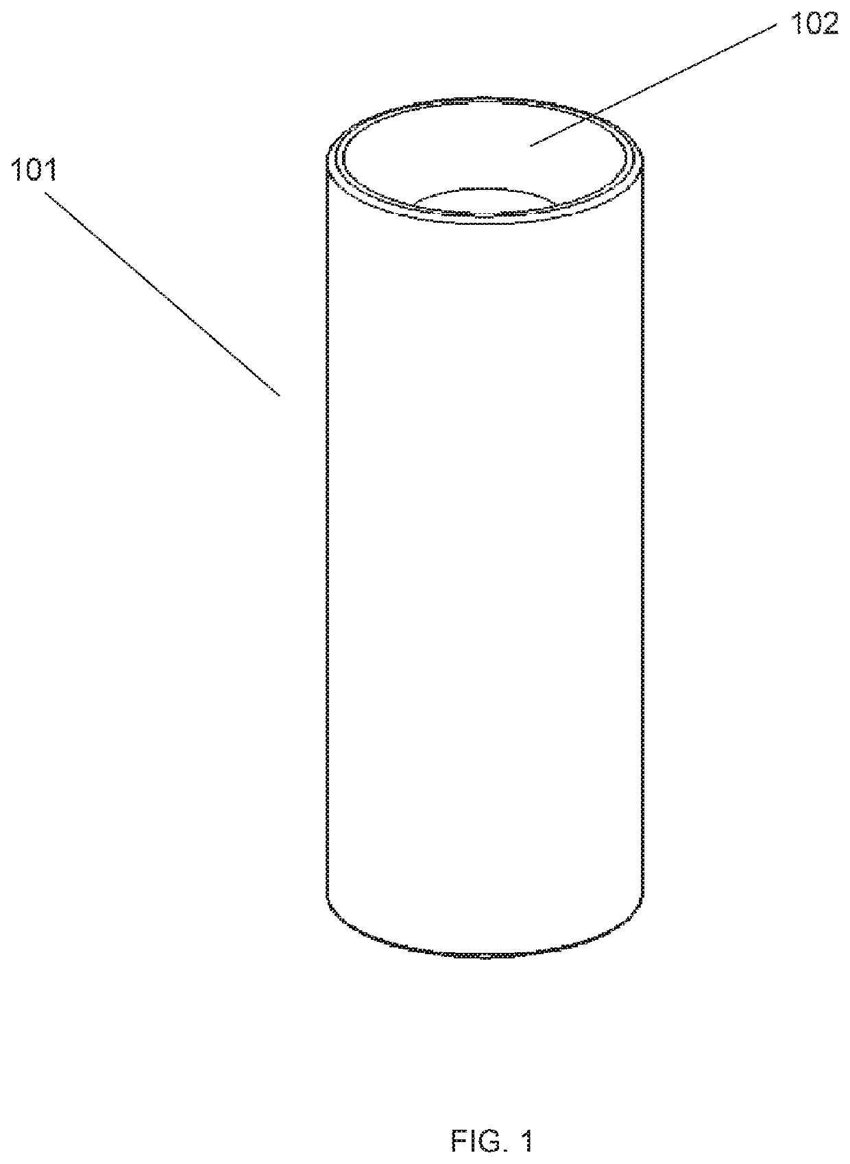
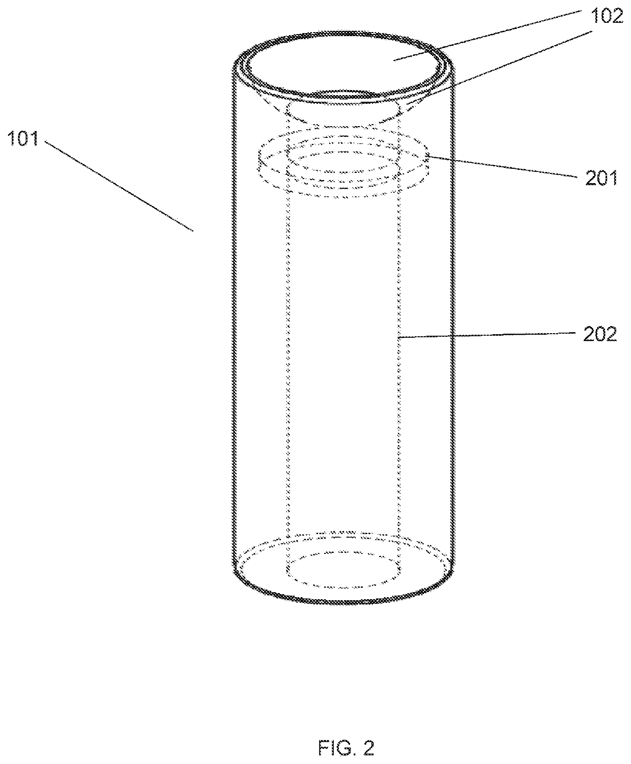
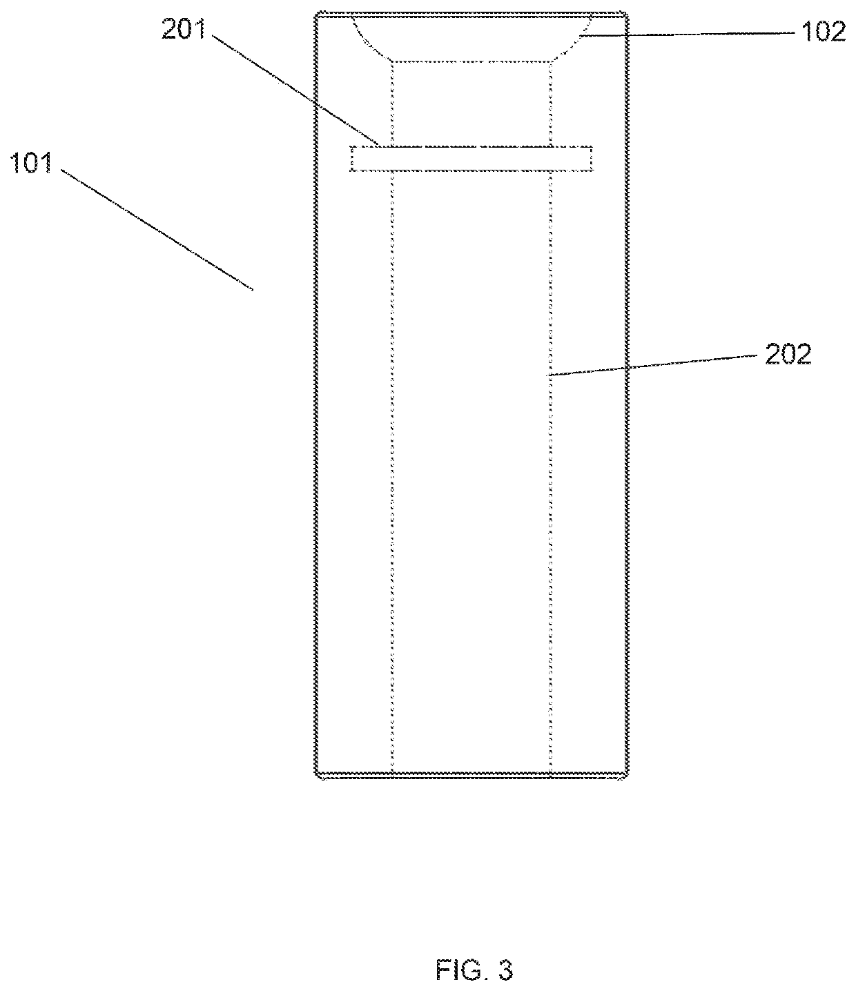
  • Ball lift sleeve and retrieval tool for oil and gas wells
  • Ball lift sleeve and retrieval tool for oil and gas wells
  • Ball lift sleeve and retrieval tool for oil and gas wells

Examples


Embodiment Construction

[0045]The best mode for carrying out the invention will be described herein. The following embodiments are described in sufficient detail to enable those skilled in the art to make and use the invention. It is to be understood that other embodiments would be evident based on the present disclosure, and that system, process, or mechanical changes may be made without departing from the scope of the present invention.

[0046]In the following description, numerous specific details are given to provide a thorough understanding of the invention. However, it will be apparent that the invention may be practiced without these specific details. To avoid obscuring the present invention, some well-known system configurations, and process steps are not disclosed in detail. The figures illustrating embodiments of the system are semi-diagrammatic and not to scale and, particularly, some of the dimensions are for the clarity of presentation and are shown exaggerated in the drawing figures.

[0047]Alter...


PUM


Abstract

A ball lift sleeve and retrieval tool comprising a sleeve for disposing in tubing of a well, the sleeve defining a first passage from a first proximal end to a first distal end, and a retrieval tool for disposing in the tubing of the well, the retrieval tool being separately moveable in the tubing between mated and unmated conditions with respect to the sleeve, the retrieval tool at least partially mating with the first distal end of the sleeve when in the mated condition and at least partially closing fluid communication through the passage of the sleeve when mated therewith.

Description

CROSS-REFERENCE TO RELATED APPLICATION[0001]This application claims the benefit of U.S. Provisional Patent Application Ser. No. 62 / 883,653 filed Aug. 7, 2019, titled “Multi-Piece Plunger,” and U.S. Provisional Patent Application Ser. No. 62 / 927,495 filed Oct. 29, 2019, titled “Ball Lift Sleeve Retrieval Tool for Oil and Gas Wells,” and the subject matter thereof is incorporated herein by reference thereto.TECHNICAL FIELD[0002]The present invention relates generally to oil and gas wells, and more particularly to ball sleeve and retrieval tool used in a multi-piece plunger lift system.BACKGROUND ART[0003]Plunger lift systems are consistently used in oil and gas wells. These systems rely on natural buildup of pressure in a shut-in gas well and gas velocity in a well struggling to flow. A bumper spring is in place at the bottom of the well where the plunger cycle begins. When the well is shut-in, the plunger falls through the gas and liquid toward the bumper spring. The plunger then tra...

Claims


Application Information

Patent Timeline
Patent Type & Authority Applications(United States)
IPC IPC(8): E21B23/00E21B33/12
CPCE21B23/00E21B33/12E21B43/121F04B47/12
Inventor ELKINS, RONSULLIVAN, ARTHUR
Owner ELK N LIZARD LLC
Why Eureka
Try Eureka