Device and method for diluting a sample

a sample and device technology, applied in the field of devices and methods for dilution samples, can solve the problems of reducing the reliability of test results and subsequent test results, reducing sample throughput, and limited measurement capability of analytical equipment for analyzing trace elements in liquids. the effect of reducing system complexity

Active Publication Date: 2011-08-16
THERMO FISHER SCIENTIFIC INC
View PDF34 Cites 13 Cited by
  • Summary
  • Abstract
  • Description
  • Claims
  • Application Information

AI Technical Summary

Benefits of technology

[0023]The embodiments have an advantage of reducing system complexity, increasing dilution factor range over which the system can operate acceptably, increasing sample throughput, and decreasing operator intervention. Providing a feedback of data from the analyser to the pump controller can provide near instantaneous automatic control of the amount by which the sample is diluted. This reduces the need for operator intervention, for instance, and can greatly improve the time efficiency of the analyser.
[0024]Embodiments of the present invention have a further advantage of a reduced number of pumps required to dilute the sample accurately before it is analysed with a substantial improvement to the range of dilution factors. The pump system and the dilution factor can be more easily controlled to better accuracy levels. The time taken to change samples for dilution is greatly reduced using embodiments of the present invention, thus increasing the number samples which might be tested by an analyser. Also, virtually no diluent is wasted during normal operation.
[0026]This further aspect has the advantage of substantially reducing the time taken to exchange samples for dilution and hence increases the number of samples which can be tested or analysed over a given time period.
[0029]Embodiments of the invention have further advantages of substantially reducing the operator intervention, and increase the sample throughput rate. The embodiments aim to provide automated dilution of the sample at a consistent and safe level before the sample is introduced into the analyser. Dilution of the sample to a safe level also has the advantage of allowing the required precision of analysis to be carried out on trace levels within the sample by automatic dilution of the sample. The sample throughput can also be increased by a relatively rapid introduction of new (or different) sample solutions up to the mixing region by controlling the flow rate of the sample uptake. The cost of diluting samples can be reduced by reducing the amount of diluent used by the dilution system; only the volume of diluent required to dilute the sample to a required safe level can be consumed and little or no diluent is wasted. (By ‘safe level’, we mean a dilution factor necessary to avoid contamination of the analysis instrumentation.)

Problems solved by technology

Analysis equipment for analysing trace elements in liquids have a limited capability of measuring samples which contain relatively high levels of dissolved solid material, or matrix (such as CaCO3 or dissolved salts in water, or the like).
Such high levels of matrix can have undesirable effects on the analytical equipment, such as deposition of materials on orifices, glassware, or ion optical elements, unless the sample is appropriately diluted.
The dissolved solids which are deposited on components within the instrument, for example on the cones which sample the plasma and skim off a portion of the supersonic jet, significantly reduces the reliability of a test result and the results of any other subsequent test.
Such manual intervention is too cumbersome, time consuming and costly if many samples per day require analysis.
These additional steps require considerable operator intervention.
Such a limit to the throughput of samples is undesirable and operator intervention is costly.
If the dilution is not maintained to a known level and within a relatively tight tolerance, the accuracy of the analysis results may be unacceptable.
Peristaltic pumps have a limited range of flow rates and the sample and diluent pumps often operate at the extremes of their flow rate range.
Also, the limited flow rate for peristaltic pumps limits the dilution factor by which the sample can be diluted.
Materials in the waste container are discarded and, since high quality diluent necessary for accurate test results is relatively expensive, this wastage is an additional economic burden on test laboratories.
The additional time required to draw the fluid into the syringe limits the laboratory's (or analysis instrument's) ability to test many samples over a period of time.
Furthermore, the time required to control the valves further limits the throughput of test samples, and extra control algorithms may be necessary for the system controller to control the valves, further increasing system complexity.
The inability to control the flow of diluent results in an uncontrolled dilution factor.
Problems arise with systems which rely on this arrangement.
For instance, there are limits to the dilution factor this system can provide, especially if the analyser requires the diluted sample to be pumped at a specific rate.
However, the problems associated with the system in FIG. 1 now become prevalent with this system, for example, diluent wastage.

Method used


Image

  • Device and method for diluting a sample
  • Device and method for diluting a sample
  • Device and method for diluting a sample

Examples


Embodiment Construction

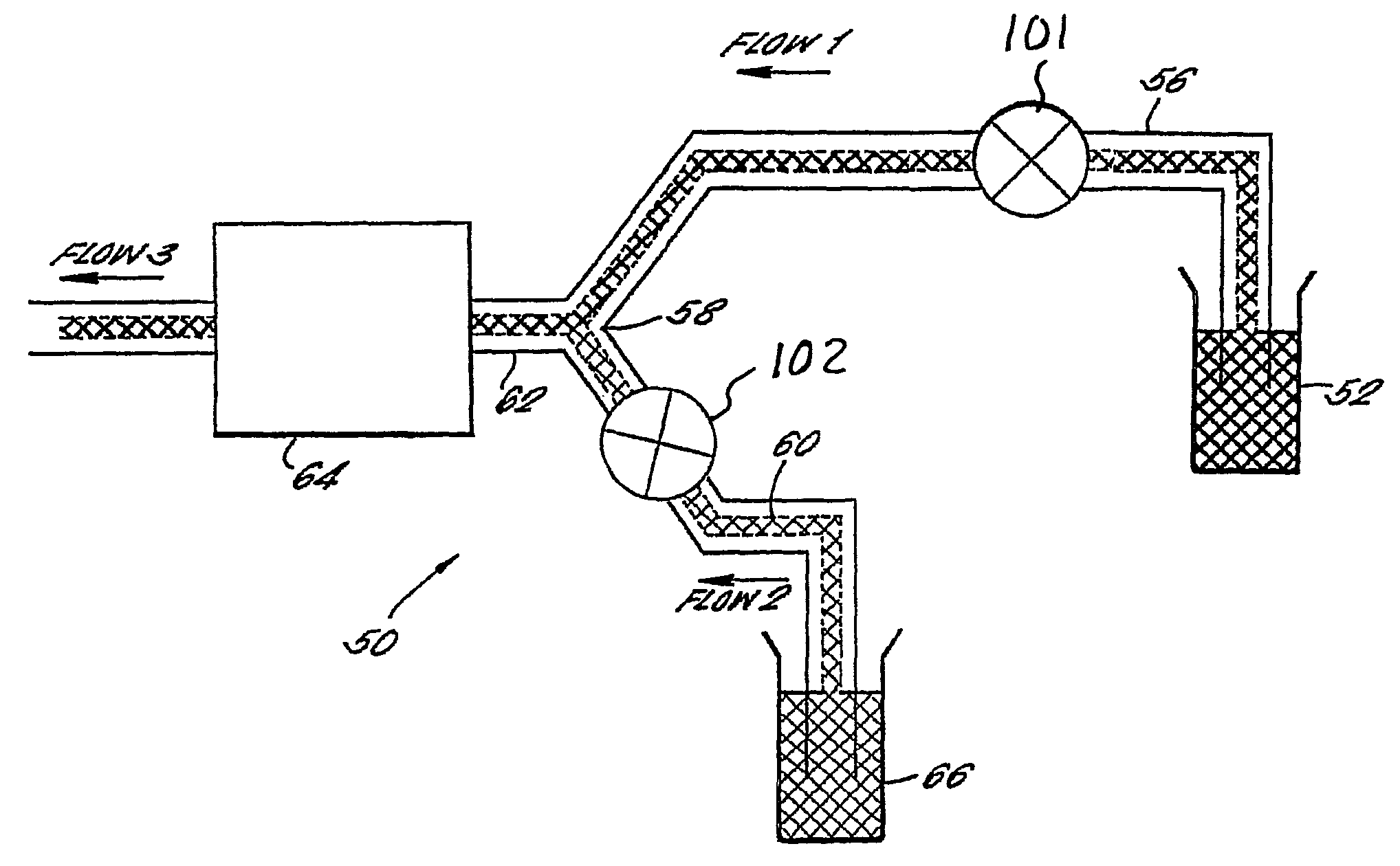
[0037]Referring to FIG. 3, a pump system 50 embodying the present invention is shown in schematic form. A sample 52 to be analysed is drawn from a container by a first pump 54 along a first pipe 56 to a mixing section 58. The end of the first pipe at which the sample enters the system is completely submersed in the sample to ensure no air enters the system. At the mixing section, the first pipe 56 is joined to a second pipe 60 to form a single pipe 62.

[0038]The mixer is a “Y” or “T” configured junction in the tubing or pipes. Other, more complex arrangements of pipe joints might be used which ensure thorough mixing of the fluids entering the mixing region from the first and second pipes. The exit of the mixing section comprises a single pipe 62 disposed between the mixing section and a second pump 64 which pumps fluid from the mixing section to an instrument (not shown) for analysis.

[0039]Mixing of the sample and diluent to form a diluted sample takes place at the interface of the f...


PUM

PropertyMeasurementUnit
massaaaaaaaaaa
mass spectrometricaaaaaaaaaa
flow rateaaaaaaaaaa

Abstract

The present invention provides a pump device 50 which is usable to dilute a sample 52 before analysis. A first pump 54 pumps the sample to a mixing region 58 where it mixes with a diluent 66. A second pump 64 pumps the diluted sample to the analysis instrument. The flow of the diluent to the mixer is equal to the difference of the flow of the sample to the mixer and the flow of the diluted sample to the instrument. Pumps 54 and 64 are independently controllable by a controller unit which is arranged so that data from the instrument can be used to determine the dilution factor of the sample. Thus, the controller can control this dilution factor in real time, upon receipt of such data from the instrument, by change either one of (or both) the pump's flow rate.

Description

PRIOR APPLICATIONS[0001]This application claims benefit of Patent Cooperation Treaty Application Number PCT / GB2003 / 003569, filed Aug. 14, 2003, which claims priority from Great Britain Application Number 0218946.2, filed Aug. 14, 2002.[0002]This invention relates to U.S. patent application Ser. No. 10 / 524,706, with an International Filing Date of Aug. 14, 2003, entitled, “Method And Apparatus For Pumping And Diluting A Sample” assigned to a common assignee.FIELD OF THE INVENTION[0003]This invention relates to a method and apparatus for diluting a sample before performing mass spectrometry on the sample.[0004]The invention is described herein with reference to liquid samples which require dilution before they are analysed in a mass spectrometer. However, the invention is not limited to liquid samples and can equally apply to dissolved or suspended samples.DESCRIPTION OF THE RELATED ART[0005]Analysis equipment for analysing trace elements in liquids have a limited capability of measur...

Claims


Application Information

Patent Timeline
Patent Type & Authority Patents(United States)
IPC IPC(8): F04B53/00G01N27/62G01N1/00G01N1/10G01N1/38
CPCG01N1/38G01N1/10Y10T436/2575Y10T436/25625
Inventor SHAW, PHILIP NEILMARRIOTT, PHILIP
Owner THERMO FISHER SCIENTIFIC INC
Why Eureka
Try Eureka