Method and system for calibration of a radio direction finder

a radio direction finder and calibration method technology, applied in direction finders using radio waves, instruments, reradiation, etc., can solve the problems of reducing the probability of interference with electromagnetic signals of the environment, limiting the duration of dwell time, signal-to-noise ratio, etc., to increase the time efficiency of measurements

Inactive Publication Date: 2006-10-26
ELTA SYST LTD
View PDF8 Cites 12 Cited by
  • Summary
  • Abstract
  • Description
  • Claims
  • Application Information

AI Technical Summary

Benefits of technology

[0027] By using the method and system of the present invention, it is not necessary to perform calibration flight at only certain hours of day or at certain locations to avoid interference.
[0028] The time synchronization technique employed by the present invention increases the time efficiency of the measurements. Moreover, contrary to the prior art technique, it does not dependent on the detection process.

Problems solved by technology

The limitation on the duration of the dwell time is associated with a magnitude of the signal-to-noise ratio required by the on-board calibration receiver.
The decrease of the dwell time decreases the probability of interference with the electromagnetic signals of the environment.

Method used


Image

  • Method and system for calibration of a radio direction finder
  • Method and system for calibration of a radio direction finder
  • Method and system for calibration of a radio direction finder

Examples


Embodiment Construction

[0062] The principles and operation of the calibration process and system according to the present invention may be better understood with reference to the drawings and the accompanying description, wherein like reference numerals have been used throughout to designate identical elements, where it is convenient for description. It is understood that these drawings are given for illustrative purposes only and are not meant to be limiting.

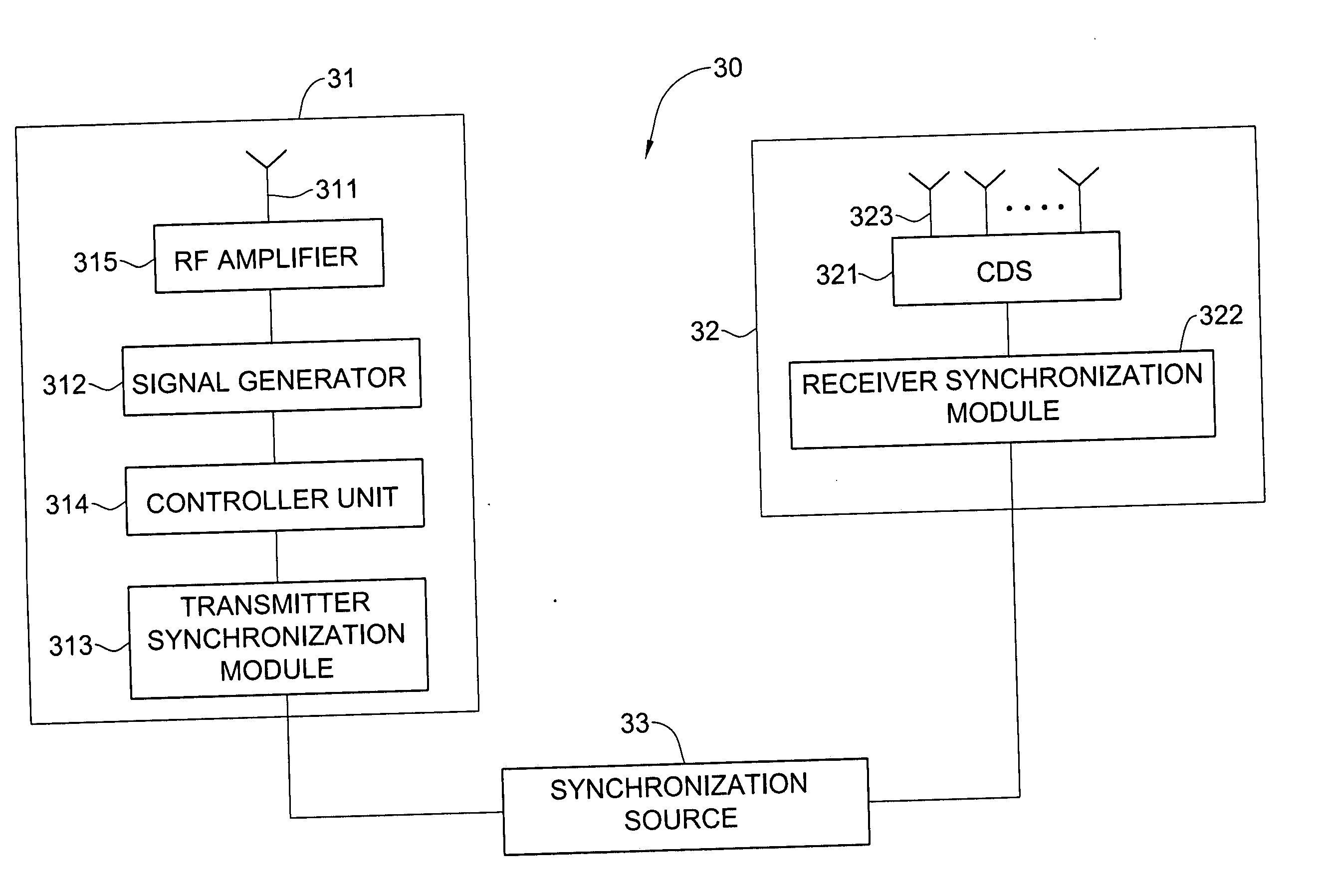
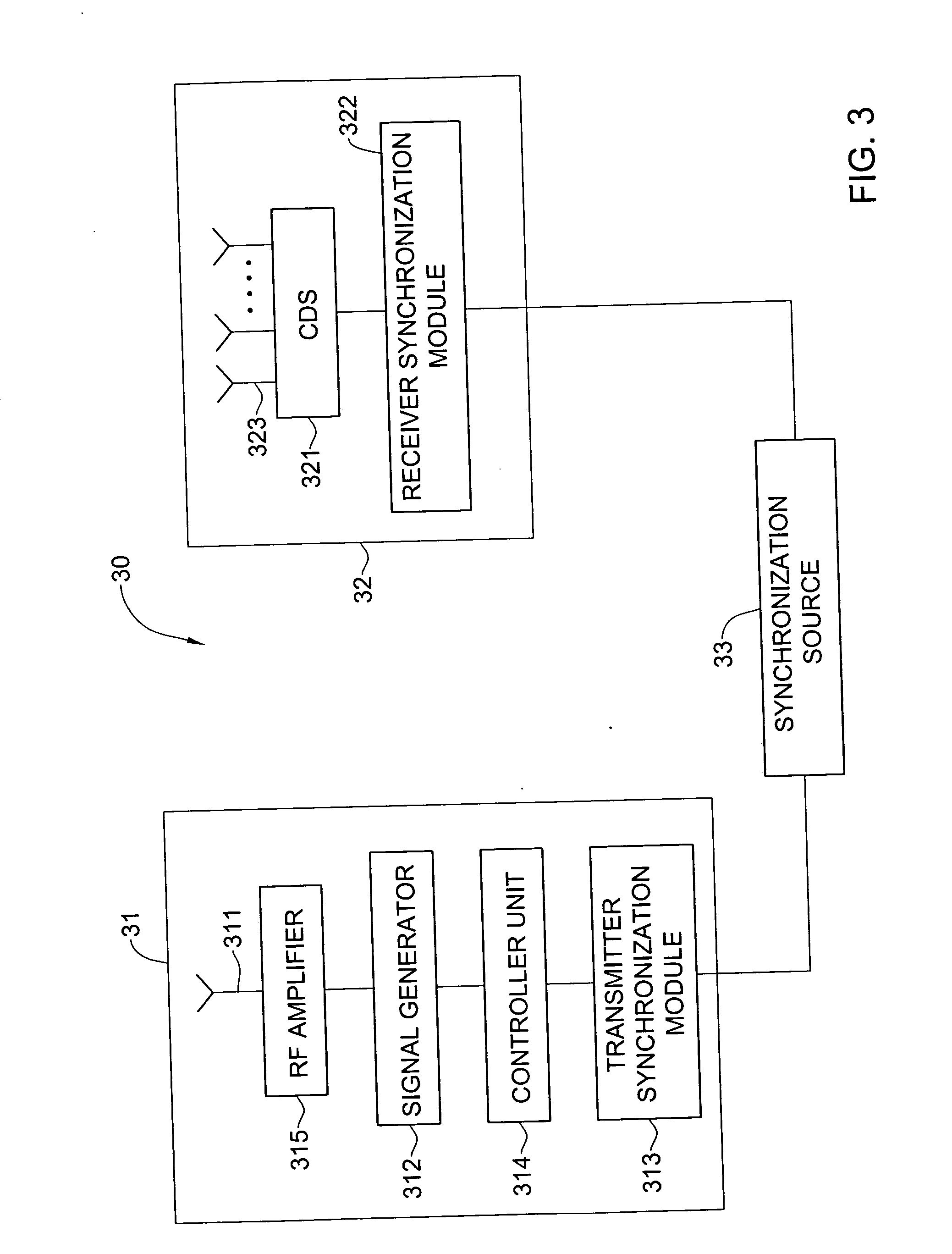
[0063] Referring to FIG. 3, a schematic block diagram of a calibration system 30 for providing calibration data is illustrated, in accordance with an embodiment of the present invention. It should be noted that the blocks in FIG. 3 are intended as functional entities only, such that the functional relationships between the entities are shown, rather than any physical connections and / or physical relationships.

[0064] The calibration system 30 includes a calibration transmitter 31, a calibration receiver 32, and a synchronization source 33 common for ...


PUM


Abstract

A calibration method and a system for providing calibration data for use with a direction finder are provided. The method comprises providing a relative motion of a calibration receiver in a circle manner with respect to calibration transmitter at a predetermined distance from each other. The method also includes preparing and transmitting a communication frequency signal employed for transmitting a certain frequency from a list of predetermined frequencies. The preparing comprises: (a) setting a value of the dwell time ranges of the communication frequency signal to a predetermined value; (b) synchronizing in time the dwell time ranges between the calibration transmitter and the calibration receiver by using clock signals of a common synchronization source; (c) providing a hop duration time interval within the dwell time range for transmitting the frequency; and (d) generating the communication frequency signal corresponding to the frequency during the hop duration interval. At the calibration receiver end, the method includes scanning the list of predetermined frequencies; intercepting a frequency signal transmitted during the hop duration time interval within the dwell time ranges; and rejecting all other frequency signals received within the dwell time ranges having duration different than the hop duration time interval by the receiver.

Description

FIELD OF THE INVENTION [0001] The present invention relates to a technique for direction finding and more particularly to a method and a system for calibrating a radio direction finder. BACKGROUND OF THE INVENTION [0002] Radio direction finders (RDF) are well known in the art as tools for finding the direction to a source of electromagnetic radiation. A direction finder may, for example, be a ground-based, an airborne or seaborne system that provides a possibility to locate or monitor various radio signal sources, stationary or movable, by determining the direction of the bearing line to the source. RDFs have many applications which may require the ability to determine the coordinates of radio source over a broad range of broadband frequencies. For instance, wideband RDFs may scan a frequency range of a few MHz to several thousand MHz. [0003] A radio direction finder utilizes an array of antennas (usually two or more) dispersed along the surface of the measurement platform. For grou...

Claims


Application Information

Patent Timeline
Patent Type & Authority Applications(United States)
IPC IPC(8): G01S7/40
CPCG01S5/021G01S3/023G01S3/02
Inventor YEHUDAIE, EFRAIM
Owner ELTA SYST LTD
Why Eureka
Try Eureka