Electric current supply system, designed to be at least partially submerged in an electrically conductive liquid during operation thereof

a technology of electrical current supply and liquid, which is applied in the direction of insulated conductors, cables, vessel construction, etc., can solve the problems of power supply failure through other electrically conductive components, damage to electric loads, and load exposur

Active Publication Date: 2022-05-03
KONINKLJIJKE PHILIPS NV
View PDF18 Cites 1 Cited by
  • Summary
  • Abstract
  • Description
  • Claims
  • Application Information

AI Technical Summary

Benefits of technology

[0010]In the electric current supply system according to the invention, the at least one electrically conductive component is designed so as to have a possibility of controlling termination of electrochemical dissolution of the material of the electrically conductive component as may be expected to take place when the electrically conductive component is exposed to water in case of damage of the system. In particular, the at least one electrically conductive component is shaped such as to have at least one well-defined position in the system where a dissolution process of the component is made to stop. In that way, when damage occurs, it is not only possible to achieve that a dumping process of electric power to the water is automatically terminated at a certain point, but also that a dissolution process of the at least one electrically conductive component cannot continue all the way to at least one electric load connected to the electrically conductive component, for example, which would otherwise cause the electric load to be exposed to the water in the end, and / or cannot continue all the way to a junction of electrically conductive components, which would otherwise cause failure of power supply through other electrically conductive components as well.
[0016]Assuming that the at least one electrically conductive component has a generally elongated shape and comprises at least one gas trap portion as mentioned, it may further be practical for the component to have a superimposed bent shape at the position of the at least one gas trap portion. In other words, it may in principle be so that the gas trap portion, seen in a larger perspective, has a more or less planar appearance, but it is also very well possible that the gas trap portion as a whole, i.e. the gas trap portion with the one or more loops or partial loops, is bent. The superimposed bent shape may contribute to the component's ability of trapping gas and / or may allow for arrangement of the component on uneven and / or bent surfaces at the position of the gas trap portion.
[0019]Optionally, the electric current supply system according to the invention is equipped with material that is made to swell as soon as it gets wet. Having such material at strategic positions in the system, which may be positions near the at least one portion of the electrically conductive component that is designed to leave behind a space in the liquid-tight material that is suitable for trapping gas should it dissolve, contributes to terminating a possible dumping process of electric current to the environment as quickly as possible.
[0025]The invention also relates to a method of reducing an outflow of electric current from an electric device comprising an electric current supply system and an electric power source, the electric current supply system comprising at least one electrically conductive component connected to the electric power source and enveloped in liquid-tight material, the outflow of electric current from the electric device occurring in the event that the electric current supply system is at least partially submerged in an electrically conductive liquid and the liquid-tight material is damaged so that the liquid is allowed to reach the at least one electrically conductive component, the at least one electrically conductive component comprising sacrificial material that is capable of reacting electrochemically with the liquid, and the method comprising: enabling an electrochemical reaction of the sacrificial material of the at least one electrically conductive component with the liquid by continuing a supply of electric current from the electric power source to the at least one electrically conductive component, and trapping gas that is generated in the electrochemical reaction in a space that is obtained in the liquid-tight material as the sacrificial material of the at least one electrically conductive component disappears at the position where the electrochemical reaction takes place. As explained earlier, the invention aims at realizing automatic termination of a situation in which electric current is dumped to an environmental electrically conductive liquid in case the at least one electrically component gets exposed to the liquid due to damage to the electric current supply system, wherein clever use is made of the gas formation effect of an electrochemical reaction between the component and the liquid, namely by trapping the gas at a position for insulating the component from the liquid.

Problems solved by technology

Another reason is that when an electric load that is arranged to be powered by means of the system receives insufficient power, this may cause damage to the electric load.
In that way, when damage occurs, it is not only possible to achieve that a dumping process of electric power to the water is automatically terminated at a certain point, but also that a dissolution process of the at least one electrically conductive component cannot continue all the way to at least one electric load connected to the electrically conductive component, for example, which would otherwise cause the electric load to be exposed to the water in the end, and / or cannot continue all the way to a junction of electrically conductive components, which would otherwise cause failure of power supply through other electrically conductive components as well.

Method used


Image

  • Electric current supply system, designed to be at least partially submerged in an electrically conductive liquid during operation thereof
  • Electric current supply system, designed to be at least partially submerged in an electrically conductive liquid during operation thereof
  • Electric current supply system, designed to be at least partially submerged in an electrically conductive liquid during operation thereof

Examples


Embodiment Construction

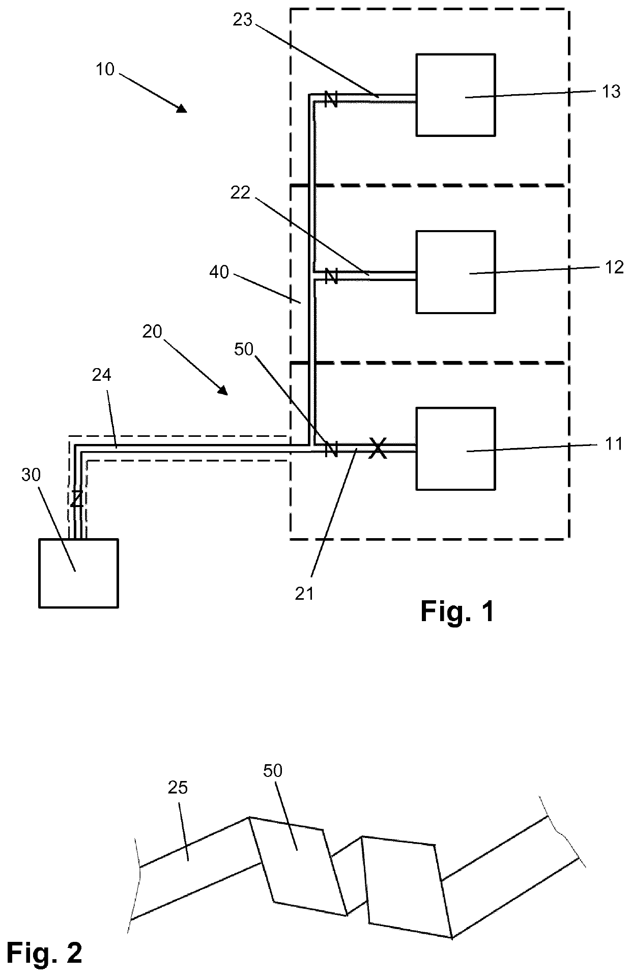
[0032]FIG. 1 provides a schematic representation of an electric device 10 comprising a number of electric loads 11, 12, 13 and an electric current supply system 20 for powering the electric loads 11, 12, 13. The number of electric loads 11, 12, 13 shown in the figure is three, which is an arbitrary number within the framework of the invention. The electric device 10 is intended to be used underwater, and may for example be arranged on a ship's hull so as to cover an area of the ship's hull. The electric loads 11, 12, 13 may be UV-C LEDs, for example, in which case the electric device 10 is suitable to be used for anti-fouling purposes, i.e. for subjecting the protected area to an anti-fouling action on the basis of which a clean appearance of the area is obtained / maintained. However, it is to be noted that the invention is not at all restricted to the field of anti-fouling, and that the present description of various aspects of the electric device 10 is equally applicable to other p...


PUM

PropertyMeasurementUnit
thicknessaaaaaaaaaa
heightaaaaaaaaaa
voltageaaaaaaaaaa

Abstract

An electric current supply system (20) is designed to be at least partially submerged in an electrically conductive liquid during operation thereof, and having at least one electrically conductive component (21, 22, 23, 24) enveloped in liquid-tight material (40). The component (21, 22, 23, 24) has a sacrificial material that is capable of reacting electrochemically with the liquid. Further, the component (21, 22, 23, 24) has at least one gas trap portion (50) at which the sacrificial material occupies a space in the liquid-tight material (40) that is thereby defined with a gas trapping shape. If, in case of damage to the system (20) in an actual submerged state thereof, the component (21, 22, 23, 24) gets exposed to the liquid, it is achieved that an electrochemical reaction occurring at the exposed area of the component (21, 22, 23, 24) and an outflow of electric current to the liquid are stopped.

Description

CROSS REFERENCE TO RELATED APPLICATIONS[0001]This application is a U.S. national phase application of International Application No. PCT / EP2018 / 079613 filed on Oct. 30, 2018, which claims the benefit of EP Application Serial No. 17199529.3 filed on Nov. 1, 2017 and are incorporated herein by reference.FIELD OF THE INVENTION[0002]The invention relates to an electric current supply system, designed to be at least partially submerged in an electrically conductive liquid during operation thereof, and comprising at least one electrically conductive component enveloped in liquid-tight material. The invention also relates to an electric device, designed to be at least partially submerged in an electrically conductive liquid during operation thereof, and comprising an electric current supply system as mentioned and at least one electric load connected to the at least one electrically conductive component of the electric current supply system. Another subject of the invention is an assembly o...

Claims


Application Information

Patent Timeline
Patent Type & Authority Patents(United States)
IPC IPC(8): B63B1/38H05B45/00C23F13/06H01B17/36H01B7/28B63B59/04H01B1/02H01B7/12B63B59/06B63B59/08
CPCH05B45/00B63B1/38C23F13/06H01B7/2813H01B17/36B63B59/04B63B59/045B63B59/06B63B59/08H01B1/023H01B1/026H01B7/12C23F13/00H05B45/40H01B5/02A61L2/10B08B17/02B08B7/0057
Inventor VISSER, CORNELIS GERARDUSVAN DELDEN, MARTINUS HERMANUS WILHELMUS MARIA
Owner KONINKLJIJKE PHILIPS NV
Why Eureka
Try Eureka