Supercharge Your Innovation With Domain-Expert AI Agents!

Deep ear sensor for reducing noise from movement and environment

a sensor and deep ear technology, applied in the field of deep ear sensors for reducing noise from movement and environment, can solve the problems of not fitting all ear canal geometries, device does not protect against sweat or bodily fluids, and is more prone to noise effects

Active Publication Date: 2022-05-10
SONOVA AG
View PDF8 Cites 0 Cited by
  • Summary
  • Abstract
  • Description
  • Claims
  • Application Information

AI Technical Summary

Problems solved by technology

Although there are many places on the body where data can be gathered (e.g., where blood vessel density and tissue type and thickness are optimal for optical transmission and reflectance), some are more prone to effects of noise caused by movement and by ambient light from the environment.
Further, the ear tip sizes are standardized and thus do not fit all ear canal geometries.
Still further, the device does not guard against sweat or bodily fluids inside the ear canal that can cover the light source and photodetector.

Method used


Image

  • Deep ear sensor for reducing noise from movement and environment
  • Deep ear sensor for reducing noise from movement and environment
  • Deep ear sensor for reducing noise from movement and environment

Examples


Embodiment Construction

[0013]Considering the above, current optical sensors for the ear suffer from poor signal quality and inaccurate measurements. Accordingly, the present disclosure relates to an in-ear optical sensor device that is capable of reducing the effects of movement and ambient light on optical signals, such as PPG signals, measured inside the ear canal.

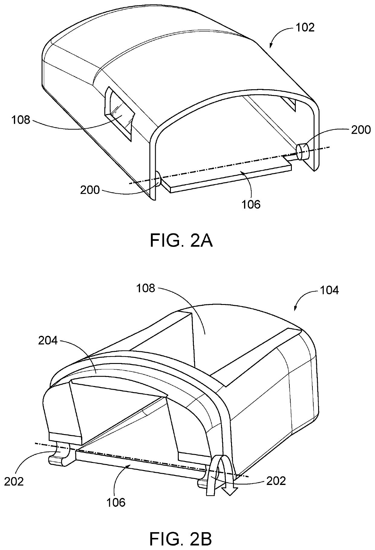
[0014]As depicted in FIGS. 1A and 1B, an example in-ear device 100 according to the present disclosure includes a lateral housing 102 and a medial head 104. Medial head 104 is a medial articulating head joined with lateral housing 102 at an articulation joint 106. The lateral housing 102 includes an audio receiver and the medial articulating head 104 includes a photodetector. One or more light sources (e.g., LEDs) can be disposed at any position on the device 100 lateral to the photodetector. In this manner, the in-ear device 100 can be inserted into the ear canal of an subject, leading with the medial articulating head 104 so that the medial ...


PUM


Abstract

An in-ear optical sensor device sits deep within the ear canal of a subject such that is in the cartilaginous region and / or the bony region of the ear canal where effects from temporomandibular joint activity or other movement, and external light, are limited. The device has a lateral housing and a medial articulating head joined at an articulation joint so that the medial articulating head may be angled relative to the lateral housing to help the device fit within tortuous ear canals. The device also includes a seal configured to conform to the shape of the ear canal to physically support the device to further limit movement and block environmental light. An audio receiver is also included in the device.

Description

BACKGROUND[0001]Optical sensors use a light source to emit light into an environment and a photodetector to detect light from the environment in order to obtain information about the environment. For instance, optical sensors of that kind are often employed to project light into tissue (e.g., skin) of a subject and a photodetector to measure reflected or transmitted light characteristics of the projected light. The detected light characteristics, a photoplethysmogram (PPG) signal, can be processed to determine heart rate, blood pressure, and other physiological properties. Although there are many places on the body where data can be gathered (e.g., where blood vessel density and tissue type and thickness are optimal for optical transmission and reflectance), some are more prone to effects of noise caused by movement and by ambient light from the environment. Additional factors that can affect quality of PPG signals include the measurement location, type of light used, movement, ligh...

Claims


Application Information

Patent Timeline
Patent Type & Authority Patents(United States)
IPC IPC(8): A61B5/00H01L31/0232H04R1/10
CPCA61B5/7228H01L31/02327H04R1/1016H04R1/1083A61B5/6817A61B5/6835A61B5/02416A61B2562/0242A61B2562/16H04R2460/15
Inventor WANG, FRANKAU, MICHAELCHRISANTI, SANTIZHU, XIUMINGZHANG, LUKHATAMI FIROOZABADI, SEYEDEH FATEMEHGARDNER, GRACE
Owner SONOVA AG
Features
  • R&D
  • Intellectual Property
  • Life Sciences
  • Materials
  • Tech Scout
  • Unparalleled Data Quality
  • Higher Quality Content
  • 60% Fewer Hallucinations
Learn More