Connectors for colorimetric sensors
a colorimetric and sensor technology, applied in the field of system and method for connecting can solve the problem of challenging mechanical system for attaching sensor arrays to sample bottles
- Summary
- Abstract
- Description
- Claims
- Application Information
AI Technical Summary
Problems solved by technology
Method used
Image
Examples
example 1
sed Connectors
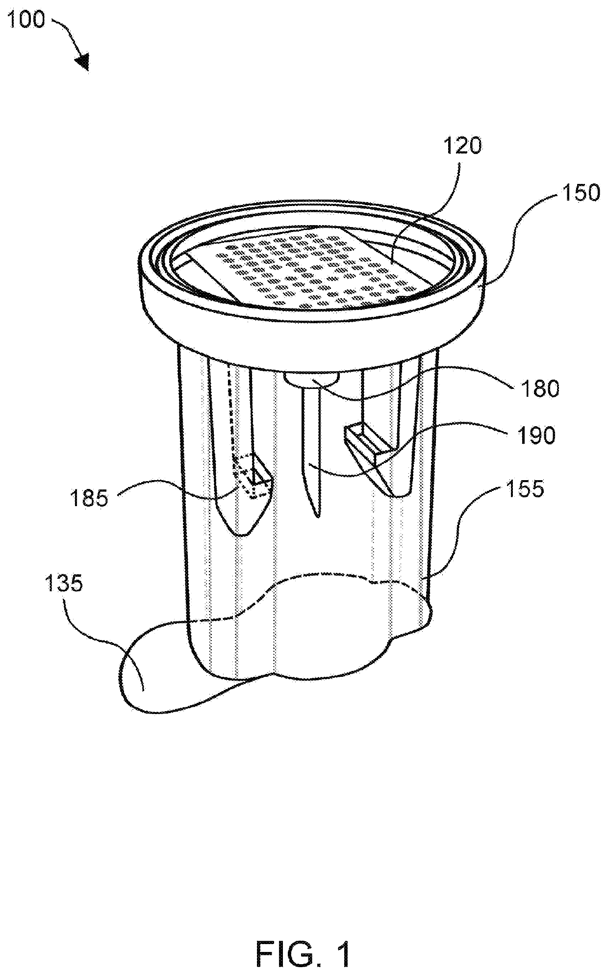
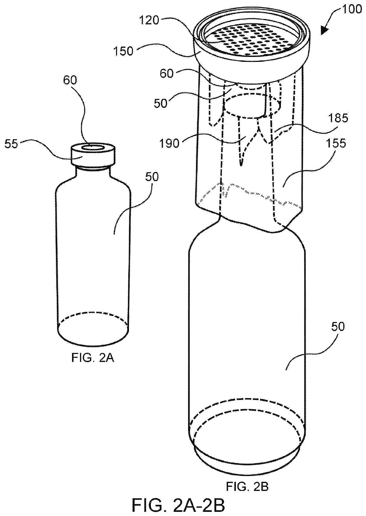
[0104]FIG. 1 illustrates an example of a connector 100 as disclosed herein. For instance, the connector 100 disclosed in FIG. 1 may be attached to a standard or conventional bottle (as shown in, e.g., FIG. 2). The connector 100 may include a top portion and a bottom portion. The top portion may be configured to connect with a compartment 150. The bottom portion may be configured to connect with a seal 135. In this example, the seal 135 may be removed from the bottom portion of the connector, which will result in a housing 155 being exposed to ambient air. The connector 100 may include a needle 190 that is configured to protrude from the top portion and be further configured to be inserted into a standard bottle 50 or other bottle with a septum 60 as illustrated in FIGS. 2A-2B. The septum 60 may be a rubber or elastic septum, or other suitable septum 60.
[0105]Referring to FIGS. 1 and 2A-2B concurrently, the connector 100 may be pushed down so that the retainers 185 clip...
example 2
ed Connectors
[0111]In another example of the present disclosure, valve based connectors 100 may be utilized. In this case, the valve based connectors 100 may connect to a conventional bottle 50 or may connect to a specialized bottle. FIG. 4A illustrates an example of a valve based connector 100 that is constructed in accordance with the principles of the present disclosure. In this example, the valve based connector 100 includes a compartment 150, a colorimetric sensor array 120 in the form of a ring, and a knob 410 connected to a valve 160 system. The knob 410 may be any dial, knob, or other actuator connected to a moveable portion of the valve 160 system integrated in the connector 100 that moves a portion of the valve 160 to open and close it. The valve system 160 when opened will form a path from the headspace gas of the bottle 50 to the compartment 150 of the CSA 120.
[0112]FIG. 4B illustrates an example of a top down view of this valve embodiment of the connector 100 that inclu...
example 3
king Connectors
[0135]FIGS. 19A-19B illustrate examples of connectors that are configured to break seals 1920 internally to allow the headspace gas to flow to the CSA 120. For instance, in some examples, a connector 100 may contain at least one protrusion 1920 that may be advanced to penetrate and break the seal 1920. The protrusion 1910 may include a spike, a rectangular or cylindrical tab, a spear, or other suitable mechanisms for piercing and opening a seal 1920. In some examples, the protrusion 1910 may have a blunt end to ensure the seal 1920 is completely punctured and not just opened.
[0136]In some examples, the seal 1920 may be a breakable plastic membrane, a metal membrane, a foil with plastic backing, or other material. Seal 1920 will have to be airtight to avoid transmission of VOCs or other microbes or contaminants until seal 1920 is broken to avoid contamination of the CSA 120.
[0137]FIGS. 19A-19B illustrate one example of how a seal may be broken, for instance in this cas...
PUM
| Property | Measurement | Unit |
|---|---|---|
| pore size | aaaaa | aaaaa |
| thickness | aaaaa | aaaaa |
| thickness | aaaaa | aaaaa |
Abstract
Description
Claims
Application Information
 - R&D
- Intellectual Property
- Life Sciences
- Materials
- Tech Scout
- Unparalleled Data Quality
- Higher Quality Content
- 60% Fewer Hallucinations
Browse by: Latest US Patents, China's latest patents, Technical Efficacy Thesaurus, Application Domain, Technology Topic, Popular Technical Reports.
© 2025 PatSnap. All rights reserved.Legal|Privacy policy|Modern Slavery Act Transparency Statement|Sitemap|About US| Contact US: help@patsnap.com


