Image forming apparatus

a technology of forming apparatus and forming tube, which is applied in the field of forming tube, can solve the problems of insufficient downsizing of the apparatus, high cost, low efficiency, etc., and achieve the effect of downsizing sufficiently

Active Publication Date: 2022-06-14
CANON KK
View PDF6 Cites 2 Cited by
  • Summary
  • Abstract
  • Description
  • Claims
  • Application Information

AI Technical Summary

Benefits of technology

[0005]The present invention provides an image forming apparatus that can be downsized sufficiently.

Problems solved by technology

According to this method, the creation of pre-printed sheets requires much time because it requires printing of a format, such as ruled lines, and the application of adhesive, and the creation of small quantities of confidential documents leads to high costs and low efficiency.
According to the image forming apparatuses disclosed in the documents mentioned above, downsizing of the apparatus was insufficient in a configuration where both a heating device, i.e., fixing unit, for fixing the printed image and a heating device, i.e., bonding unit, for carrying out the bonding process are provided.

Method used


Image

  • Image forming apparatus
  • Image forming apparatus
  • Image forming apparatus

Examples


first embodiment

Entire Configuration of Apparatus

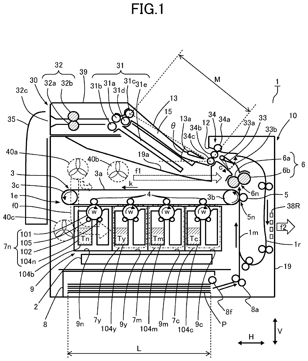
[0030]First, the entire configuration of the image forming apparatus will be described with reference to FIGS. 1, 2 and 6. FIG. 1 is a schematic drawing illustrating a sectional configuration of an image forming apparatus 1 including a main body of the image forming apparatus according to the first embodiment, hereinafter referred to as an apparatus body 10, and a postprocessing unit 30 connected to the apparatus body 10. The image forming apparatus 1 is an electrophotographic image forming apparatus, i.e., an electrophotographic system, composed of the apparatus body 10 having a printing function adopting an electrophotographic system and the postprocessing unit 30 serving as a sheet processing apparatus.

[0031]FIG. 6 is a perspective view illustrating an outer appearance of the image forming apparatus 1. The postprocessing unit 30 is attached to an upper portion of the apparatus body 10. The image forming apparatus 1 includes a sheet cassette 8 arra...

second embodiment

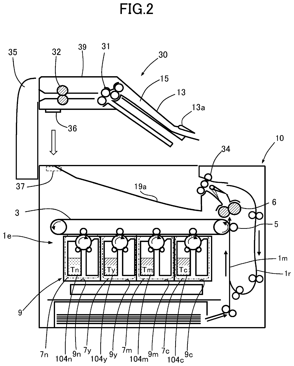
[0130]Next, a second embodiment will be described with reference to FIG. 9. The elements denoted with the same reference numbers as the first embodiment have a common function as the first embodiment, and descriptions thereof are omitted.

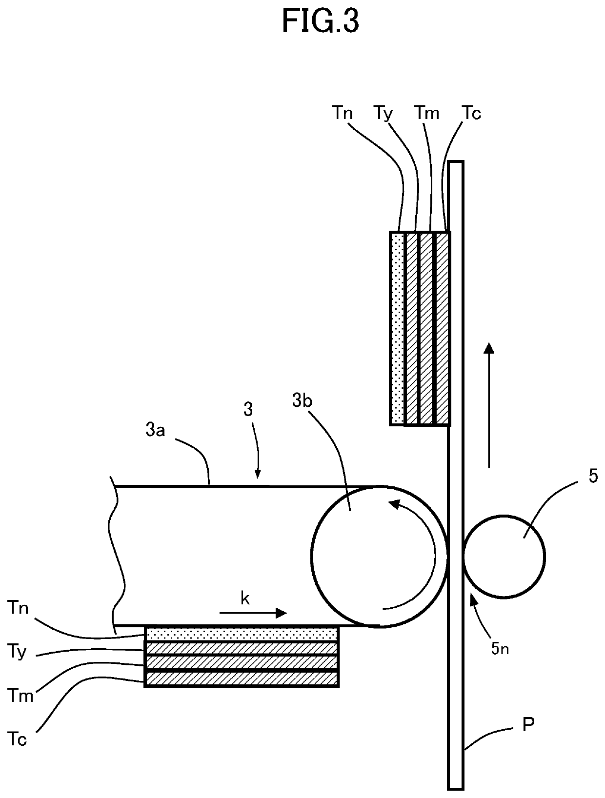
[0131]The present embodiment differs from the first embodiment in that the transfer unit 3 is arranged lower than the processing cartridges 7n, 7y, 7m and 7c. The processing cartridge 7n using the powder adhesive Tn is positioned on the rightmost side in the drawing among the four processing cartridges, and processing cartridges 7y, 7m and 7c are arranged in the named order toward the left side. The positional relationship regarding the upstream / downstream direction of cartridges with respect to the direction of rotation of the transfer belt 3a is the same as the first embodiment (FIG. 1). Therefore, as described with reference to FIG. 3, in the case of performing printing and bonding, an image of powder material of which the uppermost layer is the ...

modified example

[0134]The configuration of the invention is not limited to the example configurations illustrated in the first and second embodiments, and any configuration is preferable as long as the air heated by cooling the heat source of the image forming apparatus 1 does not easily reach the powder storage portion 104n storing the powder adhesive Tn. For example, if the second fixing unit 32 is arranged in the casing of the apparatus body 10 according to the configuration, the second fixing unit 32 should preferably be arranged downstream of the powder storage portion 104n in the air blow route that passes the powder storage portion 104n. That is, with respect to the direction from the fan 40 via the powder storage portion 104n to the louver 38L, at least one of the fixing portion, the bonding portion and the powder storage portions 104y, 104m and 104c should preferably be arranged downstream of the powder storage portion 104n. The direction that passes the powder storage portion 104n toward ...


PUM

PropertyMeasurementUnit
widthaaaaaaaaaa
timeaaaaaaaaaa
thicknessaaaaaaaaaa

Abstract

An image forming apparatus includes, an image forming portion configured to form a toner image on a sheet using printing toner and apply powder adhesive on the sheet, a fixing portion configured to heat the toner image formed on the sheet and the powder adhesive applied on the sheet by the image forming portion and fix the toner image and the powder adhesive to the sheet, and a bonding portion configured to bond the sheet with the powder adhesive by reheating the sheet having been heated by the fixing portion. The bonding portion is arranged above the image forming portion.

Description

BACKGROUND OF THE INVENTIONField of the Invention[0001]The present invention relates to an image forming apparatus for forming an image on a sheet.Description of the Related Art[0002]Hitherto, in order to create a confidential document that requires sealing, such as a salary payment statement (also called as salary slip or payslip), a pre-printed sheet is prepared in advance, and variable data is printed to each pre-printed sheet, before the sheet is subjected to a sealing process performed as postprocessing. According to this method, the creation of pre-printed sheets requires much time because it requires printing of a format, such as ruled lines, and the application of adhesive, and the creation of small quantities of confidential documents leads to high costs and low efficiency.[0003]Japanese Patent Application Laid-Open Publication Nos. 2006-171607 and 2007-193004 teach an image forming apparatus that uses powder adhesive in addition to printing toner to execute an electrophoto...

Claims


Application Information

Patent Timeline
Patent Type & Authority Patents(United States)
IPC IPC(8): G03G15/20G03G15/00
CPCG03G15/2053G03G15/6582G03G15/6544G03G21/1604G03G2221/1696G03G2215/00848G03G2215/00877G03G15/6573B65H2801/27B65H45/142
Inventor YAMAGUCHI, KOJIMATSUDA, KOHEIOGINO, HIROKIKATSUTA, YASUSHINOGUCHI, KAORIHIRATA, JUNKOKURODA, AKIRANISHIZAWA, YUKISHIMANO, TSUTOMUOGUMA, TORU
Owner CANON KK
Why Eureka
Try Eureka