Device and method for performing sternotomy

a sternotomy and sternectomy technology, applied in the field of medical science, surgery, endoscopy, etc., can solve the problems of blade vibration, achieve the effect of avoiding excessive and unnecessary heat generation, facilitating mid-sternal cutting, and ensuring the accuracy of the sawing process

Active Publication Date: 2022-06-28
BULSUBASIC NEDA
View PDF7 Cites 0 Cited by
  • Summary
  • Abstract
  • Description
  • Claims
  • Application Information

AI Technical Summary

Benefits of technology

[0017]In another embodiment the electrocautery blade can be connected to a switch that is activated when an electrocautery switch is engaged and / or backward pressure (resistance) is sensed as the saw is advanced against the soft tissues under the sternum. This switch can regulate or interrupt the current delivered to the electrocautery blade and it can prevent excessive and unnecessary heat generated when the electrocautery is not resisted by the soft tissue. In another embodiment, the switch is not connected to the electrocautery blade itself but is connected to the beam (connector and / or motor housing) that is connecting the base of the saw and the body of the saw.
[0018]In another embodiment, the sternal saw has a disposable saw blade that is oriented forward and upward and is used to cut the sternum after it is separated from the structures underlying the sternum. In another embodiment, the disposable or reusable saw blade is visible from the top of the saw and the line of vision of the operator to the blade is unobstructed unlike most current saws on the market. An unobstructed view of the blade and the cutting plane allows much more precise maneuvering of the saw to facilitate a mid-sternal cut.
[0019]In another embodiment, the dissecting baseplate containing the electrocautery blade can be connected to the body of the saw by a post made of hardened steel, titanium or another material that has extremely high tensile strength to be able to sustain the force applied and to prevent bending during lifting and cutting of the sternum during the use of the saw. To ensure easy sliding along the cut made in the sternum, the width of the connecting post has to be smaller than the width of the cut made by the saw blade. In addition to the width of the post, the front of the post can be tapered and rounded to reduce resistance and facilitate sliding along the sternotomy cut.

Problems solved by technology

The device can further comprise a vibrator that results in vibration of the blade.

Method used


Image

  • Device and method for performing sternotomy
  • Device and method for performing sternotomy
  • Device and method for performing sternotomy

Examples


Embodiment Construction

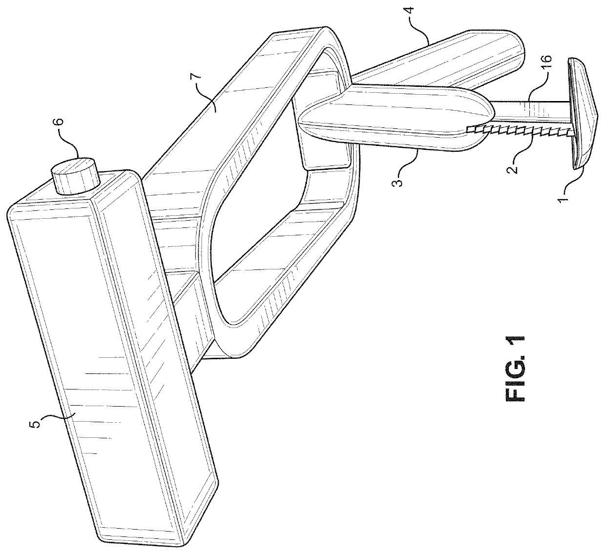
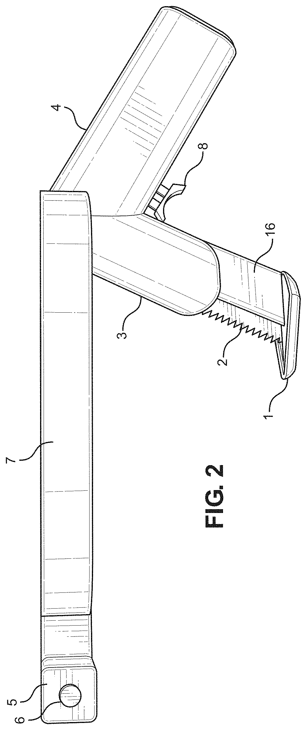
[0050]FIG. 1 illustrates a bottom perspective view of the device. The saw is shown with base 1, a blade 2 positioned on top of base 1, a post and / or motor housing 3 for connecting to both base connector 16 and blade 2. Body 7 is positioned on top of post and / or motor housing 3. The body 7 is connected at one end to handle 4 and at another end to handle 5.

[0051]The base 1 is configured to be placed below the sternum as the device cuts the sternum. The base 1 is configured to separate the sternum from the tissue below. The base 1 can have a leading angular edge (such as triangular / V-shaped) that is oriented towards the person's head as the saw cuts the sternum. The angle can be about 10 degrees to about 50 degrees, such as about 20 to 40 degrees. The top of the base 1 can be flat and bottom of the base 1 can be curved. The base 1 can have straight sides with curved edges. The base 1 can be a triangular shape with a maximum height of 2 mm to 10 mm. The maximum front to back length of t...


PUM


Abstract

Provided is a surgical saw for cutting a sternum comprising: a) a body, b) a handle attached to the body; c) a blade positioned in such way to cut the sternum when a user holds the handle, and d) a base below the blade configured to be positioned below the sternum, wherein the user places the base under the sternum and cuts the sternum with the blade.

Description

CROSS-REFERENCE[0001]The present application claims the benefit of U.S. provisional application No. 62 / 713,660, filed on Aug. 2, 2018, and 62 / 720,872, filed on Aug. 21, 2018, both of which are incorporated herein by reference in their entirety.FIELD OF THE INVENTION[0002]This invention relates generally to surgical instrument, surgical sternal saw, more particularly, to a sternal saw that can comprise an integrated radiofrequency blade and a camera positioned in a way that would allow visualization of simultaneous separation of a sternum from underlying structures, coagulation of the periostial blood vessels and safe cutting of the sternum while visualizing tissue plane during the procedure, thereby protecting the underlying cardiac and vascular structures from mechanical injury or damage from electrocautery blade.BACKGROUND SECTION OF THE INVENTION[0003]Repeated, known as re-do cardiac surgery, has dramatically higher morbidity and mortality risk when compared to first cardiac surg...

Claims


Application Information

Patent Timeline
Patent Type & Authority Patents(United States)
IPC IPC(8): A61B17/14A61B17/16A61B18/14A61B34/20A61B18/00
CPCA61B17/142A61B17/1691A61B18/14A61B34/20A61B2018/00196A61B2018/00607A61B2018/1412A61B2034/2055A61B18/082A61B2018/00565A61B2018/00982A61B90/361A61B2090/309A61B2017/00424A61B17/144
Inventor BULSUBASIC, NEDA
Owner BULSUBASIC NEDA
Why Eureka
Try Eureka