Fuel cell

Active Publication Date: 2012-01-12
HONDA MOTOR CO LTD
View PDF3 Cites 7 Cited by
  • Summary
  • Abstract
  • Description
  • Claims
  • Application Information

AI Technical Summary

Benefits of technology

[0011]Further, in Japanese Laid-Open Patent Publication No. 2005-085520, the ring-shaped metal cover has a large number of gas outlets formed at predetermined intervals over the entire circumferential side portion of the metal cover, and the metal cover and the separator are provided as separate components. Therefore, a larger number of components are required, the structure is complicated, and the cost is high. Further, a larger number of assembling steps are required, and thus, the operating efficiency is low. Further, the dimension in the thickness direction is large, and the length of the entire stack in the stacking direction is large.
[0022]Further, gases other than the fuel gas, such as the oxygen-containing gas and the exhaust gas do not flow around to the anode from the outside of the electrolyte electrode assembly. Therefore, degradation in the power generation efficiency due to oxidation of the anode is prevented, and improvement in the durability of the separator and the electrolyte electrode assembly is achieved easily.

Problems solved by technology

In Japanese Laid-Open Patent Publication No. 10-172594, since seals are provided, in comparison with seal-less structure, excessive loads tend to be applied to the MEAs.
Therefore, for example, the MEAs may be cracked or damaged undesirably.
Further, Japanese Laid-Open Patent Publication No. 10-172594 is not directed to a technique of suitably preventing the fuel gas, the oxygen-containing gas, or the exhaust gas from unnecessarily flowing around.
Therefore, a larger number of components are required, the structure is complicated, and the cost is high.
Further, a larger number of assembling steps are required, and thus, the operating efficiency is low.
As a result, the electrodes may be degraded undesirably, and power generation performance may be lowered undesirably.

Method used


Image

  • Fuel cell
  • Fuel cell
  • Fuel cell

Examples


first embodiment

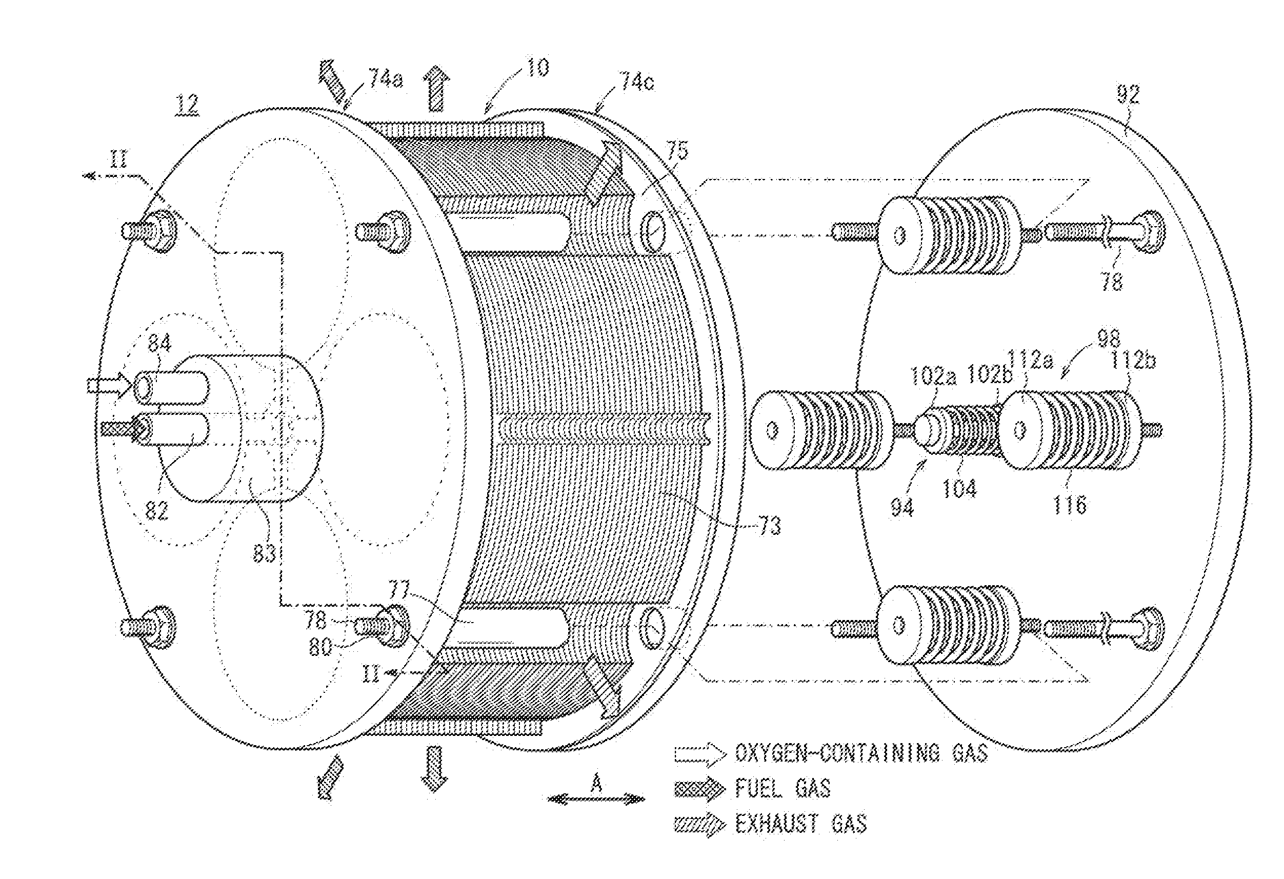
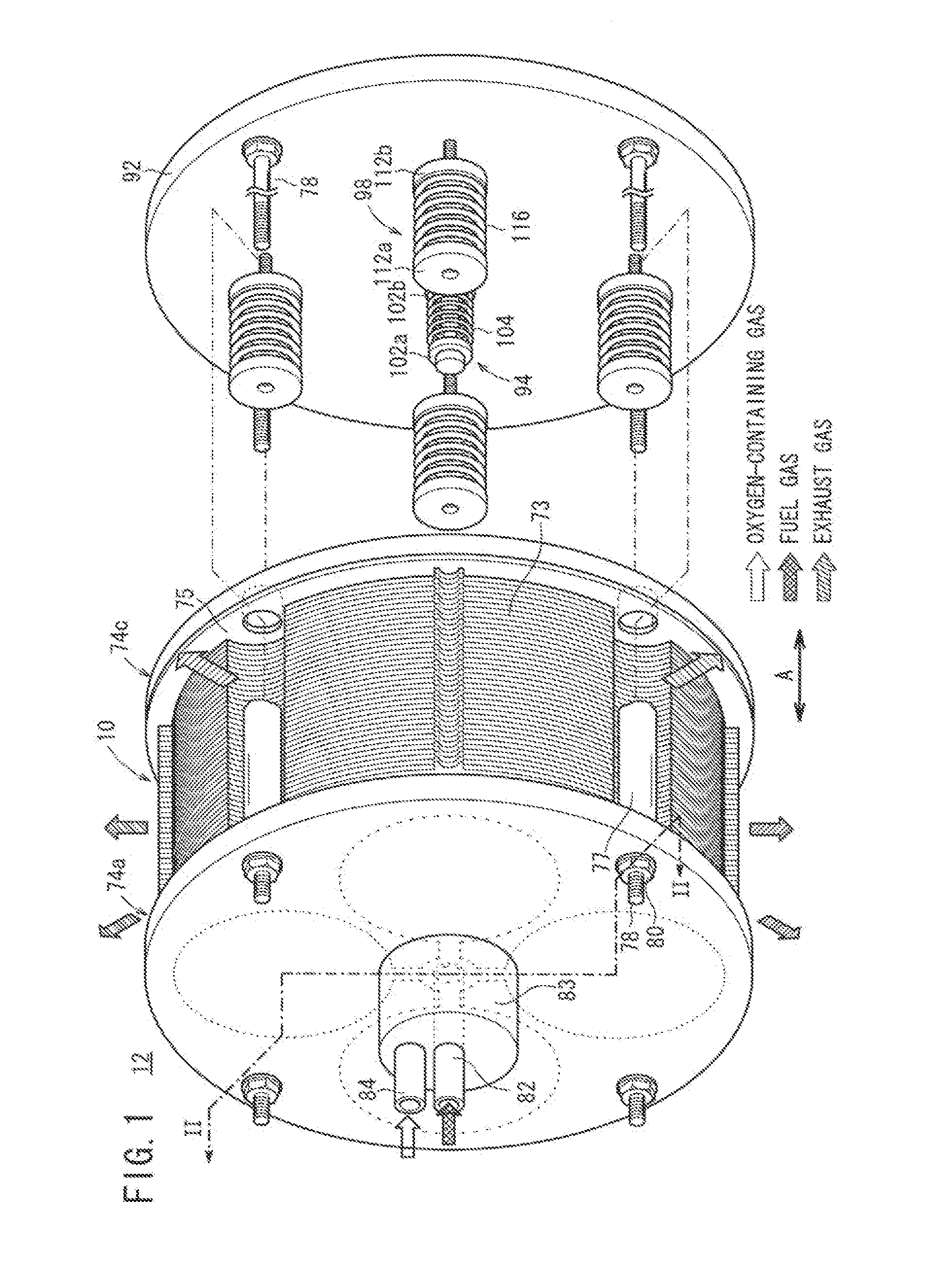
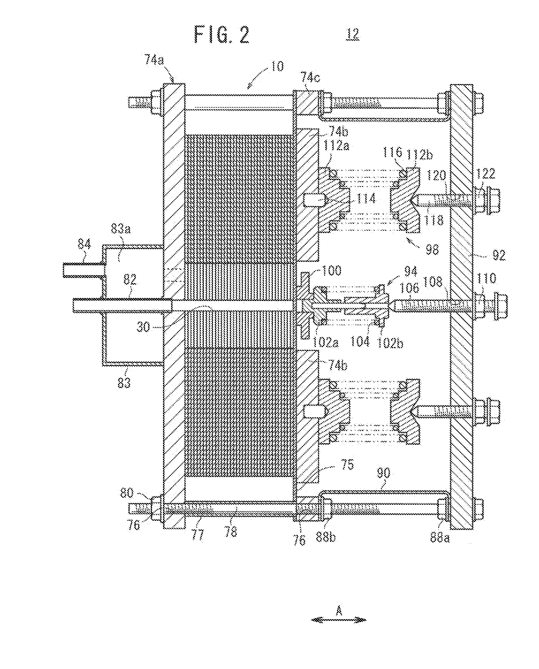
[0042]As shown in FIGS. 1 and 2, a fuel cell according to the present invention is formed by stacking a plurality of fuel cells 10 in a direction indicated by an arrow A. The fuel cell 10 is a solid oxide fuel cell (SOFC) used in various applications, including stationary and mobile applications. For example, the fuel cell 10 is mounted on a vehicle.

[0043]As shown in FIGS. 3 and 4, the fuel cell 10 includes electrolyte electrode assemblies (MEAs) 26. Each of the electrolyte electrode assemblies 26 includes a cathode 22, an anode 24, and an electrolyte (electrolyte plate) 20 interposed between the cathode 22 and the anode 24. For example, the electrolyte 20 is made of ion-conductive oxide such as stabilized zirconia. The electrolyte electrode assembly 26 has a circular disk shape. A barrier layer (not shown) is provided at least at the outer circumferential edge of the electrolyte electrode assembly 26 for preventing entry or discharge of the oxygen-containing gas and the fuel gas.

[0...

second embodiment

[0107]In the second embodiment, the oxygen-containing gas flows along the cathode 22 from the outside of the first and second sandwiching sections 36, 58 toward the first and second fuel gas supply sections 32, 52. In the structure, it is possible to prevent the other gases such as the oxygen-containing gas and the exhaust gas from flowing around to the anode 24 from the outside of the electrolyte electrode assembly 26. Thus, degradation of the power generation efficiency due to oxidation of the anode 24 is prevented, and improvement in the durability of the separator 142 and the electrolyte electrode assembly 26 is achieved.

[0108]In the second embodiment, the oxygen-containing gas flows in directions indicated by the arrows D, and the gas flow directions at the fuel gas outlet channels 144a, 144b, 144c are the directions indicated by the arrows C. The directions indicated by the arrows D and the directions indicated by the arrows C intersect each other. In the structure, it is poss...

third embodiment

[0113]FIG. 9 is an exploded perspective view showing a fuel cell 150 according to the present invention.

[0114]The fuel cell 150 includes separators 152, and each of the separators 152 is formed by joining a first plate 152a and a second plate 152b together. A pair of fuel gas outlet channels 154a, a pair of fuel gas outlet channels 154b, and a pair of fuel gas outlet channels 154c are provided on a surface 36a of each of first sandwiching sections 36 of the first plate 152a. A fuel gas partially consumed in the fuel gas channel 40 is discharged through the fuel gas outlet channels 154a, 154b, 154c.

[0115]The fuel gas outlet channels 154a, 154b, 154c are provided on a side opposite to a portion connecting the first sandwiching section 36 and the first bridge 34, on both sides of an extended line L of the first bridge 34 at equal intervals. In the fuel gas outlet channels 154a, 154b, 154c, the cross sectional area on the downstream side in the gas flow direction of the fuel gas along ...


PUM


Abstract

A fuel cell is provided with a separator that supports an electrolyte / electrode assembly sandwiched therebetween. The separator is provided with: first and second fuel gas supply parts in the center of which fuel gas supply holes are formed; first and second cross-link parts connected to the first and second fuel gas supply parts; and first and second surrounding support parts connected to the first and second cross-link parts. Each first surrounding support part is provided with a set of fuel gas exhaust passages that discharge fuel gas that has gone through a fuel gas passage and been used. The cross-sectional areas of the fuel gas exhaust passages are larger on the downstream sides than on the upstream sides, in terms of the direction of fuel gas flow.

Description

TECHNICAL FIELD[0001]The present invention relates to a fuel cell formed by sandwiching electrolyte electrode assemblies between separators. Each of the electrolyte electrode assemblies includes an anode, a cathode, and an electrolyte interposed between the anode and the cathode.BACKGROUND ART[0002]Typically, a solid oxide fuel cell (SOFC) employs an electrolyte of ion-conductive oxide such as stabilized zirconia. The electrolyte is interposed between an anode and a cathode to form an electrolyte electrode assembly (MEA). The electrolyte electrode assembly is interposed between separators (bipolar plates). In use, predetermined numbers of the electrolyte electrode assemblies and the separators are stacked together to form a fuel cell stack.[0003]For example, in a flat plate type solid oxide fuel cell disclosed in Japanese Laid-Open Patent Publication No. 10-172594, a separator 1a as shown in FIG. 17 is provided, and a plurality of unit cells (not shown) and separators 1a are stacked...

Claims


Application Information

Patent Timeline
IPC IPC(8): H01M8/24H01M8/10
CPCH01M8/0247H01M8/0258H01M8/04067H01M8/243H01M8/248H01M8/2465H01M2250/20Y02E60/50Y02E60/525Y02T90/32H01M2008/1293H01M8/2432H01M8/2457H01M8/2483H01M8/2484Y02T90/40H01M8/2459
Inventor OGAWA, TETSUYAKIYOHIRO, YUKIHIKODAN, KOJIYOSHIMINE, YUKI
Owner HONDA MOTOR CO LTD
Why Eureka
Try Eureka