
Determining a length of a timeout period

a timeout period and timeout time technology, applied in the direction of digital transmission, transmission path sub-channel allocation, high-level techniques, etc., to achieve the effect of reducing traffic load, sharing network resources, and saving power

Active Publication Date: 2022-06-28
SIGNIFY HLDG BV
View PDF8 Cites 0 Cited by
  • Summary
  • Abstract
  • Description
  • Claims
  • Application Information

AI Technical Summary

Benefits of technology

This approach enables accurate identification of the timeout period, optimizing message scheduling, reducing power consumption, and ensuring continuous communication by setting appropriate intervals for periodic messages, thereby enhancing network efficiency and device reachability.

Problems solved by technology

This is with the intention of saving power, as devices in some wireless networks are resource-restricted.

Method used


Image

  • Determining a length of a timeout period
  • Determining a length of a timeout period
  • Determining a length of a timeout period

Examples


Embodiment Construction

[0058]The invention will be described with reference to the Figures.

[0059]It should be understood that the detailed description and specific examples, while indicating exemplary embodiments of the apparatus, systems and methods, are intended for purposes of illustration only and are not intended to limit the scope of the invention. These and other features, aspects, and advantages of the apparatus, systems and methods of the present invention will become better understood from the following description, appended claims, and accompanying drawings. It should be understood that the Figures are merely schematic and are not drawn to scale. It should also be understood that the same reference numerals are used throughout the Figures to indicate the same or similar parts.

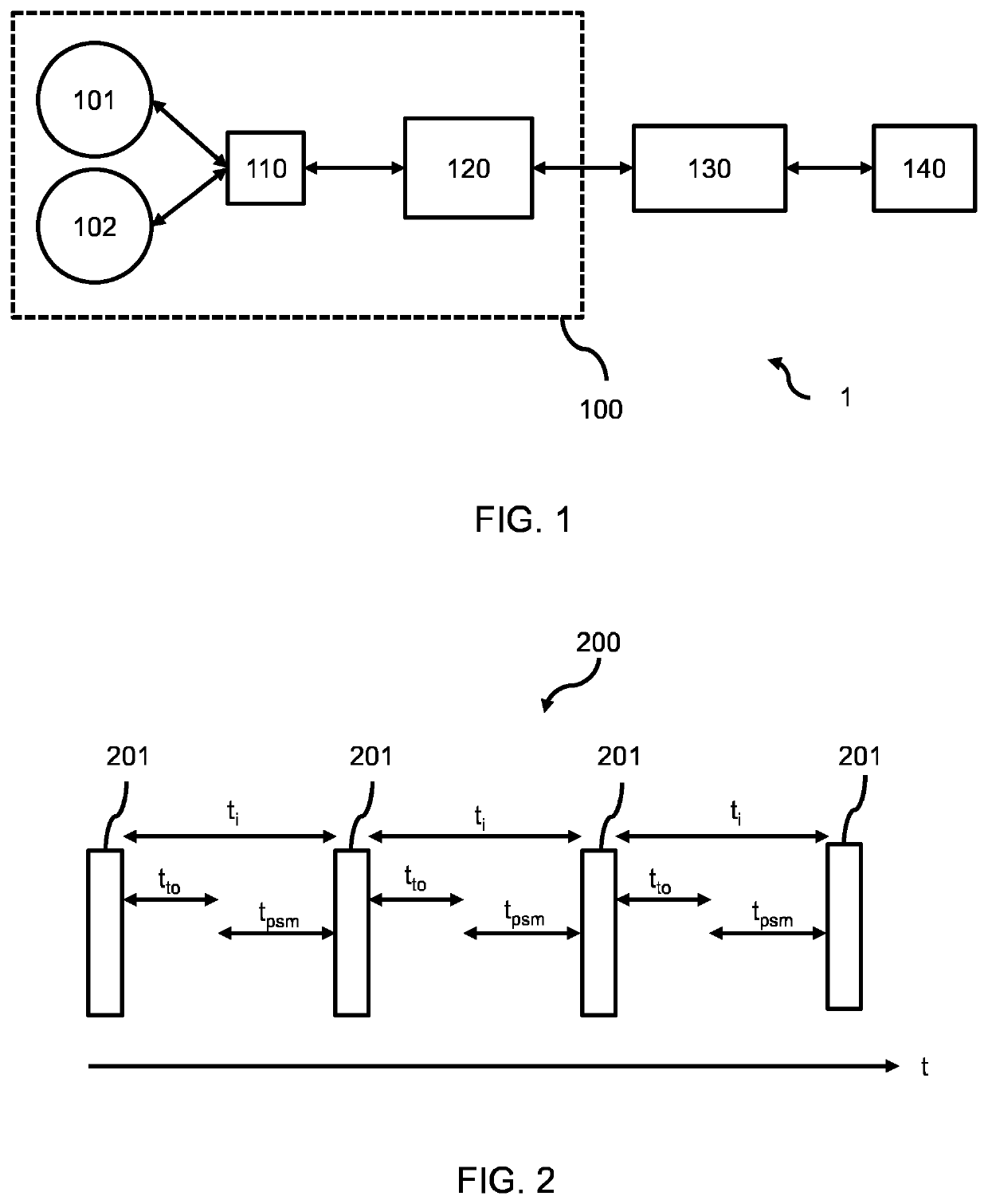
[0060]According to a concept of the invention, there is proposed a method for determining information about a length of a timeout period, which represents a length of time without communication after which a device of a fi...


PUM


Abstract

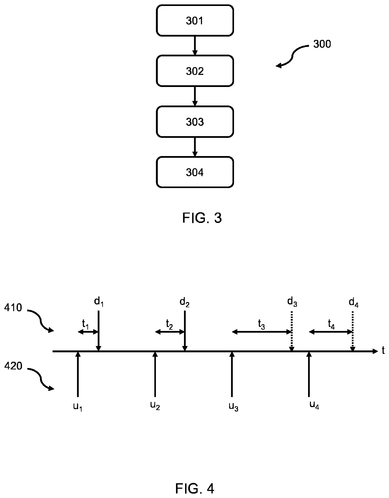
A method for determining information about a length of a timeout period, which represents a length of time without communication after which a device of a first type becomes unreachable. Information about the timings of successful and unsuccessful message sent to the device(s) of a first type is obtained, alongside information about the timings of messages sent by the device(s) of the first type, and used to calculate the length of a timeout period.

Description

CROSS-REFERENCE TO PRIOR APPLICATIONS[0001]This application is the U.S. National Phase application under 35 U.S.C. § 371 of International Application No. PCT / EP2019 / 077498, filed on Oct. 10, 2019, which claims the benefits of European Patent Application No. 18213598.8, filed on Dec. 18, 2018 and Chinese Patent Application No. PCT / CN2018 / 110839, filed on Oct. 18, 2018. These applications are hereby incorporated by reference herein.FIELD OF THE INVENTION[0002]The invention relates to the field of wireless networks, and in particular to methods of determining communication information of nodes of wireless networks.BACKGROUND OF THE INVENTION[0003]Wireless networks are becoming increasingly common. One example of a wireless network is a Low-Power Wide-Area Network (LPWAN), which has been proposed to fill a technological gap that exists between the well-known technologies of wireless sensor networks and wide area networks. A LPWAN is a wireless Wide-Area network technology specialized fo...

Claims


Application Information

Patent Timeline
Patent Type & Authority Patents(United States)
IPC IPC(8): H04L5/00
CPCH04L5/0058H04L5/0078H04L67/12Y02D30/70
Inventor FENG, LEI
Owner SIGNIFY HLDG BV
Learn More