Coupling device

a technology of coupling device and flange, which is applied in the direction of hose connection, flanged joint, fastening means, etc., can solve the problems that the clamp type cannot be applied to a flange of a specific size and cannot be applied to a flange of a larger or smaller size, so as to achieve the effect of tightening the flange of the pip

Active Publication Date: 2022-07-12
CHEN YUAN LAI +1
View PDF7 Cites 0 Cited by
  • Summary
  • Abstract
  • Description
  • Claims
  • Application Information

AI Technical Summary

Benefits of technology

[0006]The main object of the present invention is to provide a coupling device which can effectively tighten flanges of pipes with various sizes.

Problems solved by technology

That is, this type of clamp can only be applied to a flange of a specific size and cannot be applied to a flange of larger or smaller size.

Method used


Image

  • Coupling device
  • Coupling device
  • Coupling device

Examples


Embodiment Construction

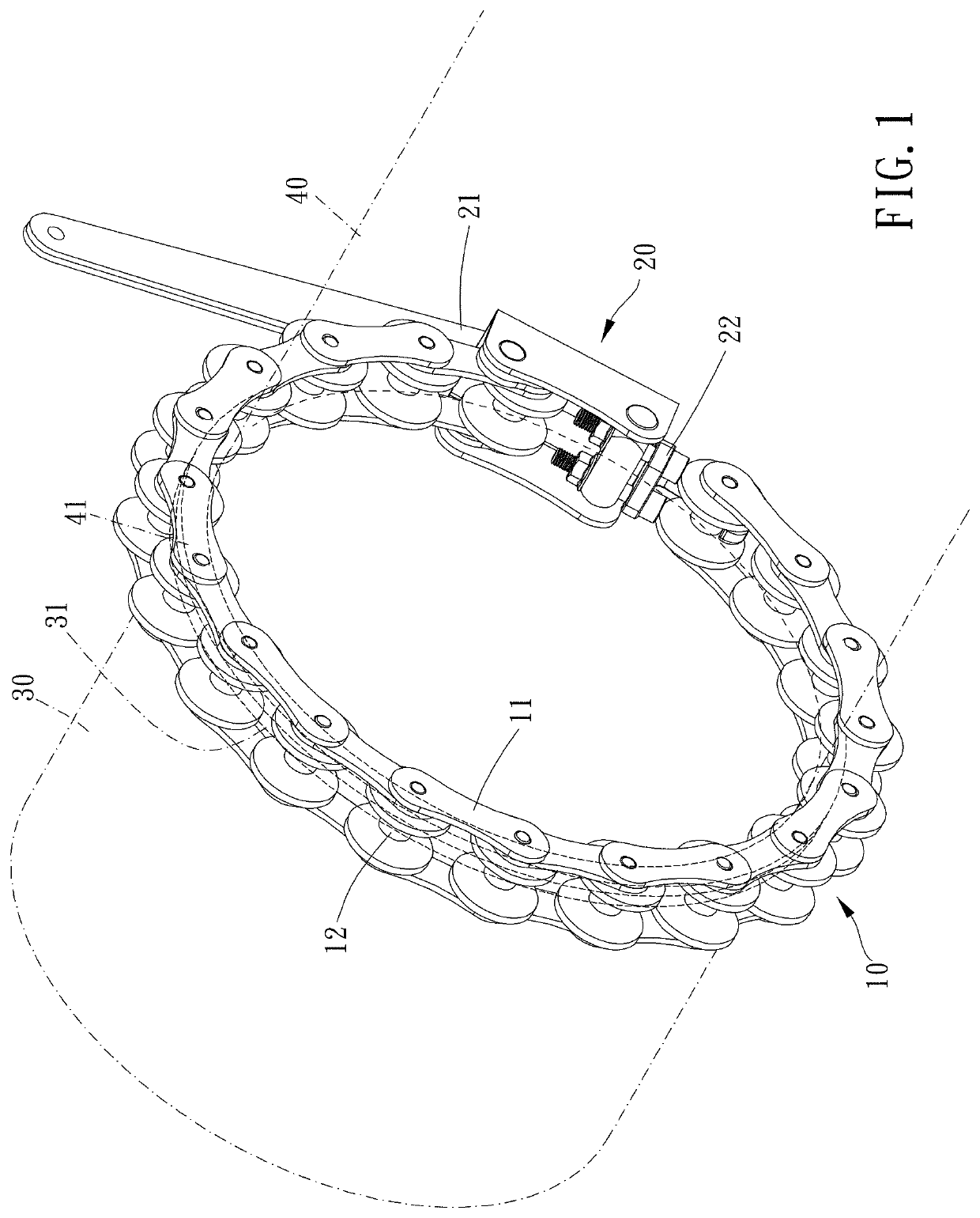
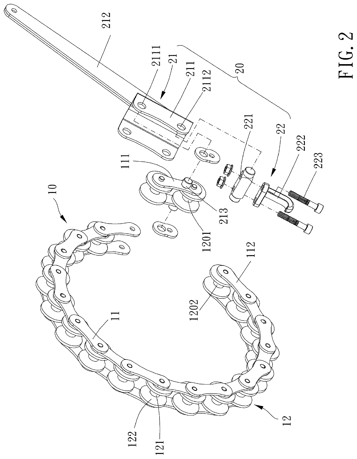
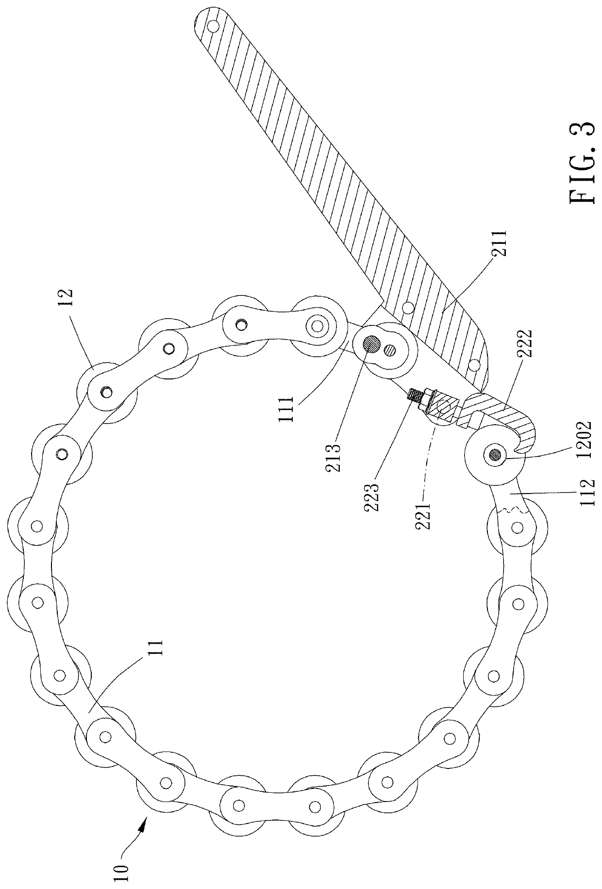
[0013]Please refer to FIGS. 1 to 5 for a preferable embodiment of the present invention. A coupling device 1 of the present invention is configured for coupling flanges of two pipes. The coupling device 1 includes a chain assembly 10, 10′ and a positioning mechanism 20.

[0014]The chain assembly 10, 10′ includes a plurality of connecting pieces 11, 11′ and a plurality of pivot members 12, and the plurality of connecting pieces 11, 11′ are pivotally connected one by one by the plurality of pivot members 12 to be chain-like. One of the plurality of connecting pieces 11 at one of two opposite ends of the chain assembly 10, 10′ is defined as a first connecting piece 111, and a free end of the first connecting piece 111 has a first pivot member 1201. Another one of the plurality of connecting pieces 11 at the other of the two opposite ends of the chain assembly 10, 10′ is defined as a second connecting piece 112, and a free end of the second connecting piece 112 has a second pivot member 1...


PUM


Abstract

A coupling device for coupling flanges of two pipes includes a chain assembly and a positioning mechanism. The chain assembly includes plural connecting pieces pivotally connected one by one by pivot members. The connecting pieces at two opposite ends of the chain assembly are defined as a first connecting piece and a second connecting piece. A first pivot member is arranged at the free end of the first connecting piece, and a second pivot member is arranged at the free end of the second connecting piece. The positioning mechanism includes a first portion and a second portion pivotally connected. The first portion is pivotally connected to the first pivot member or the first connecting piece, and the second portion is detachably positioned to the second pivot member. The first portion is rotatable between a release position and a fixed position relative to the second portion.

Description

BACKGROUND OF THE INVENTIONField of the Invention[0001]The present invention relates to a coupling device.Description of the Prior Art[0002]Generally, it is usually to use irreversible fixing means such as welding, adhesion to connect two pipes. However, if two pipes have to be separated, other temporary connection fixing means (screwing or clamping) could be used.[0003]A typical flange clamp as disclosed in U.S. Pat. No. 5,522,625, usually includes two semicircular bodies and a fixing mechanism connected between the two semicircular bodies. The two semicircular bodies are disposed on flanges of two pipes, and the then the two semicircular bodies are tightened by the fixing mechanism to fixedly couple the two pipes.[0004]However, the shape and size of the clamp surface of this type of structure depends on the inner surface of the two semicircular bodies. That is, this type of clamp can only be applied to a flange of a specific size and cannot be applied to a flange of larger or smal...

Claims


Application Information

Patent Timeline
Patent Type & Authority Patents(United States)
IPC IPC(8): F16L23/10F16L23/06F16L33/12
CPCF16L23/10F16L23/06F16L33/12F16B2/185F16B2/08
Inventor CHEN, YUAN-LAILIU, DA-TAN
Owner CHEN YUAN LAI
Why Eureka
Try Eureka