Terminal

a terminal and pin technology, applied in the field of terminals, can solve problems such as enlarging the width of the pin contact element, and achieve the effect of suppressing the width of the plate-like terminal

Active Publication Date: 2022-07-12
AUTONETWORKS TECH LTD +2
View PDF14 Cites 2 Cited by
  • Summary
  • Abstract
  • Description
  • Claims
  • Application Information

AI Technical Summary

Benefits of technology

[0039]According to the terminal disclosed in this specification, it is possible to suppress a width of a plate-like terminal including an insulating member on a front end.

Problems solved by technology

Since the contact protection member is molded integrally to the housing, the both side edges of the contact member are covered by the contact protection member, thereby causing a problem of enlarging a width of the pin contact element.

Method used


Image

  • Terminal
  • Terminal
  • Terminal

Examples


first embodiment

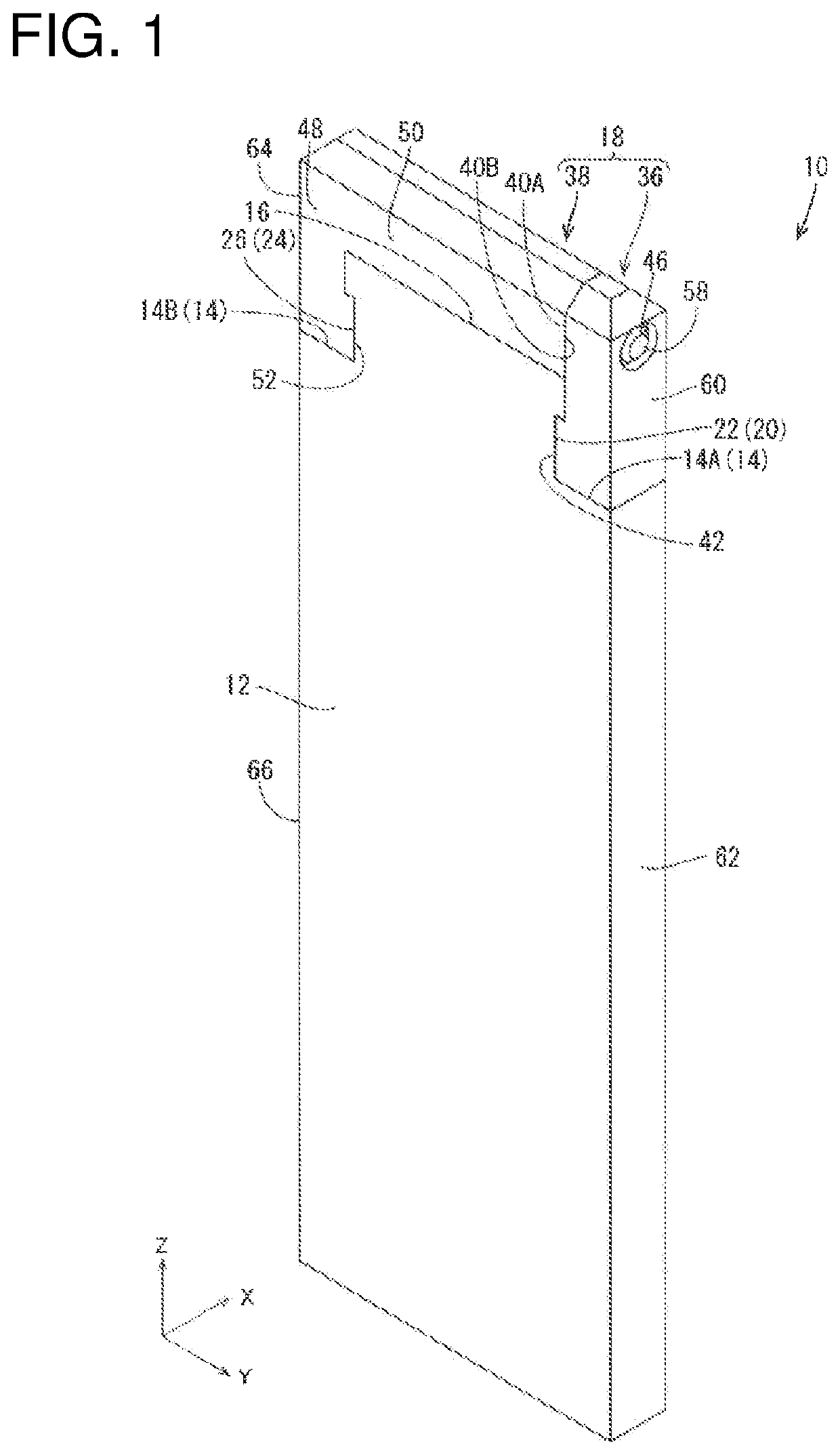
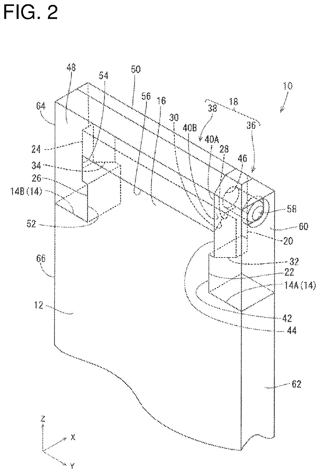
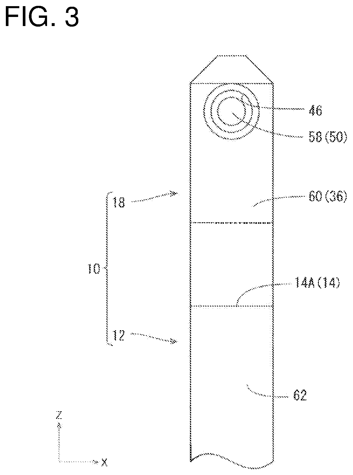
[0066]A plate terminal (terminal) 10 of a first embodiment is described with reference to FIGS. 1 to 11. In the following description, an upward direction of FIG. 6 (Z direction of FIG. 6) is referred to as a forward direction, which is a connecting direction of the plate terminal 10, a downward direction of FIG. 6 is referred to as a rearward direction, a rightward direction of FIG. 6 (Y direction of FIG. 6) is referred to as one width direction of the plate terminal 10, and a leftward direction of FIG. 6 is referred to as another width direction of the plate terminal 10. Further, a rightward direction of FIG. 3 (X direction of FIG. 3) is referred to as one thickness direction of the plate terminal 10, and a leftward direction of FIG. 3 is referred to as another thickness direction of the plate terminal 10.

[0067]The plate terminal 10 is mounted in a housing (not shown) made of resin and, as shown in FIGS. 1 and 2, composed of a body portion 12 made of metal and in the form of a pla...

second embodiment

[0096]A plate terminal 10A of a second embodiment is described with reference to FIGS. 12 to 16. In the plate terminal 10A, an insulating member 18A is composed of one member unlike the plate terminal 10 of the first embodiment.

[0097]As shown in FIGS. 15 and 16, the plate terminal 10A is composed of a body portion 12 made of metal and in the form of a plate long in the front-rear direction, a plate-like mounting portion 16A connected to the body portion 12 and projecting forward from a front end surface 14 of the body portion 12, and a separate insulating member 18 to be mounted on the mounting portion 16 from front.

[0098]A groove-like first recess 22 is provided in a first side surface 20, which is a side surface on one widthwise side of the mounting portion 16A, and a groove-like second recess 26 is provided in a second side surface 24, which is a side surface on another other widthwise side of the mounting portion 16A.

[0099]A first inclined surface 30 inclined toward a front end ...

third embodiment

[0114]A plate terminal 10B of a third embodiment is described with reference to FIGS. 17 and 18. An insulating member 18B of the plate terminal 10B is composed of one member similarly to the plate terminal 10A of the second embodiment, but mounted on a mounting portion 16A by insert molding unlike the plate terminal 10A of the second embodiment.

[0115]A first insulating member 36B and a first covering portion 48A of a second insulating member 38B of the insulating member 18B are configured not to be resiliently displaceable in the width direction unlike the plate terminal 10A in the second embodiment, so that the insulating member 18B is less likely to be detached from the mounting portion 16A than in the plate terminal 10A of the second embodiment.


PUM


Abstract

A plate terminal 10 disclosed by this specification is provided with a plate-like body portion 12 made of metal and long in a front-rear direction, and a plate-like mounting portion 16 connected to the body portion 12 and projecting forward from a front end surface 14 of the body portion 12, a separate insulating member 18 being mounted on the mounting portion 16. The insulating member 18 is located forward of the front end surface 14 of the body portion 12 and covers at least parts of a front end surface 28 of the mounting portion 16 and the front end surface 14 of the body portion 12.

Description

CROSS REFERENCE TO RELATED APPLICATIONS[0001]This application is a national phase of PCT application No. PCT / JP2019 / 001624, filed on 21 Jan. 2019, which claims priority from Japanese patent application Nos. 2018-119823 and 2018-170432 filed on 25 Jun. 2018 and 12 Sep. 2018, respectively, all of which are incorporated herein by reference.TECHNICAL FIELD[0002]A technique disclosed by this specification relates to a terminal.BACKGROUND[0003]A pin contact element described in Japanese National Publication of International Patent Application No. 2016-522550 (Patent Document 1 below) is known as an example of a conventional terminal. The pin contact element is shaped into a flat contact and includes a contact member and a contact protection member formed integrally to the contact member. The contact protection member covers an upper part and both side edges of the contact member, and a contact surface of the contact member is exposed to outside.[0004]The pin contact element is provided in...

Claims


Application Information

Patent Timeline
Patent Type & Authority Patents(United States)
IPC IPC(8): H01R13/44H01R13/04
CPCH01R13/44H01R13/04H01R43/16
Inventor SHIMIZU, TORUKOBAYASHI, SHINGOBYUN, SUNGHYUN
Owner AUTONETWORKS TECH LTD
Why Eureka
Try Eureka