
Optical disk device and optical disk recording method

a technology of optical disk and recording method, which is applied in the direction of overwriting/replacing recorded data, digital signal error detection/correction, instruments, etc., can solve the problems of increasing the error rate, user data cannot be appropriately rewritten, and the wobble signal cannot be appropriately detected

Inactive Publication Date: 2005-02-03
FUNAI ELECTRIC CO LTD
View PDF6 Cites 2 Cited by
  • Summary
  • Abstract
  • Description
  • Claims
  • Application Information

AI Technical Summary

Benefits of technology

[0009] An object of this invention is to provide an optical disk device capable of reducing the error rate during reproduction and of appropriately performing rewriting recording by suppressing a difference between the recording position of data when it is newly written and the recording position of the data at the previous time.
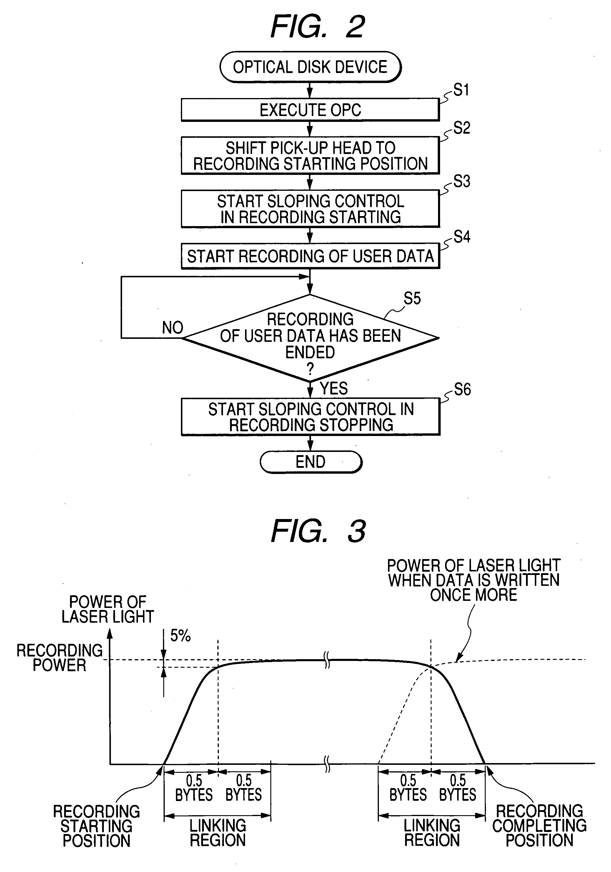
[0012] In accordance with this configuration, when data recording is ended, the power of laser light irradiated onto the linking region is decreased on the basis of the first condition by the laser power control unit. Thus, the width of marks (pits) formed in the linking region is suppressed. For this reason, interference between the signal indicative of the marks formed in the linking region and a wobble signal can be suppressed, thereby appropriately detecting the wobble signal. Thus, when the user data is newly written or rewritten, deviation of the recoding position of the user data at this time from the recording position of the user data at the previous time can be reduced. Accordingly, the error rate during reproduction can be reduced, and the data previously recorded can be surely erased during rewriting recording, thereby permitting the rewriting of the user data to be appropriately performed.
[0016] According to yet another aspect of the present invention an optical disk recording method including acquiring recording power, recording data on an optical disk by irradiating laser light of the recording power onto the optical disk, and controlling power of the laser light. Preferably, the recording power is suited to record data on the optical disk, and the controlling power of the laser light includes gradually decreasing the power of the laser light irradiated in a linking region from the recording power based on a first prescribed condition when recording of data by the recording unit is ended and gradually increasing the power of the laser light irradiated in the linking region to the recording power based on a second prescribed condition when the recording of data by the recording unit is started.

Problems solved by technology

Meanwhile, in the region where pits (inclusive of the user data and mark in the linking region) are formed, a signals indicative of the pits and a wobble signal interfere with each other so that as the case may be, the wobble signal cannot be appropriately detected.
As a result, when the user data is written once, the wobble signal cannot be appropriately detected so that the previous recording position of the user data and the present recording position of the user data are deviated from each other in a width direction of a track, thereby leading to a problem of increasing the error rate.
Particularly, the rewritable type has a problem that when another user data is recorded on the region where the user data has been already recorded, the recording position is changed so that the user date recorded is not completely erased and so the user data cannot be appropriately rewritten.

Method used


Image

  • Optical disk device and optical disk recording method
  • Optical disk device and optical disk recording method
  • Optical disk device and optical disk recording method

Examples


Embodiment Construction

[0023] Hereafter, an explanation will be given of an optical disk device which is an embodiment of this invention.

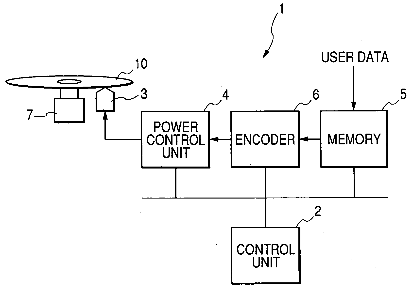
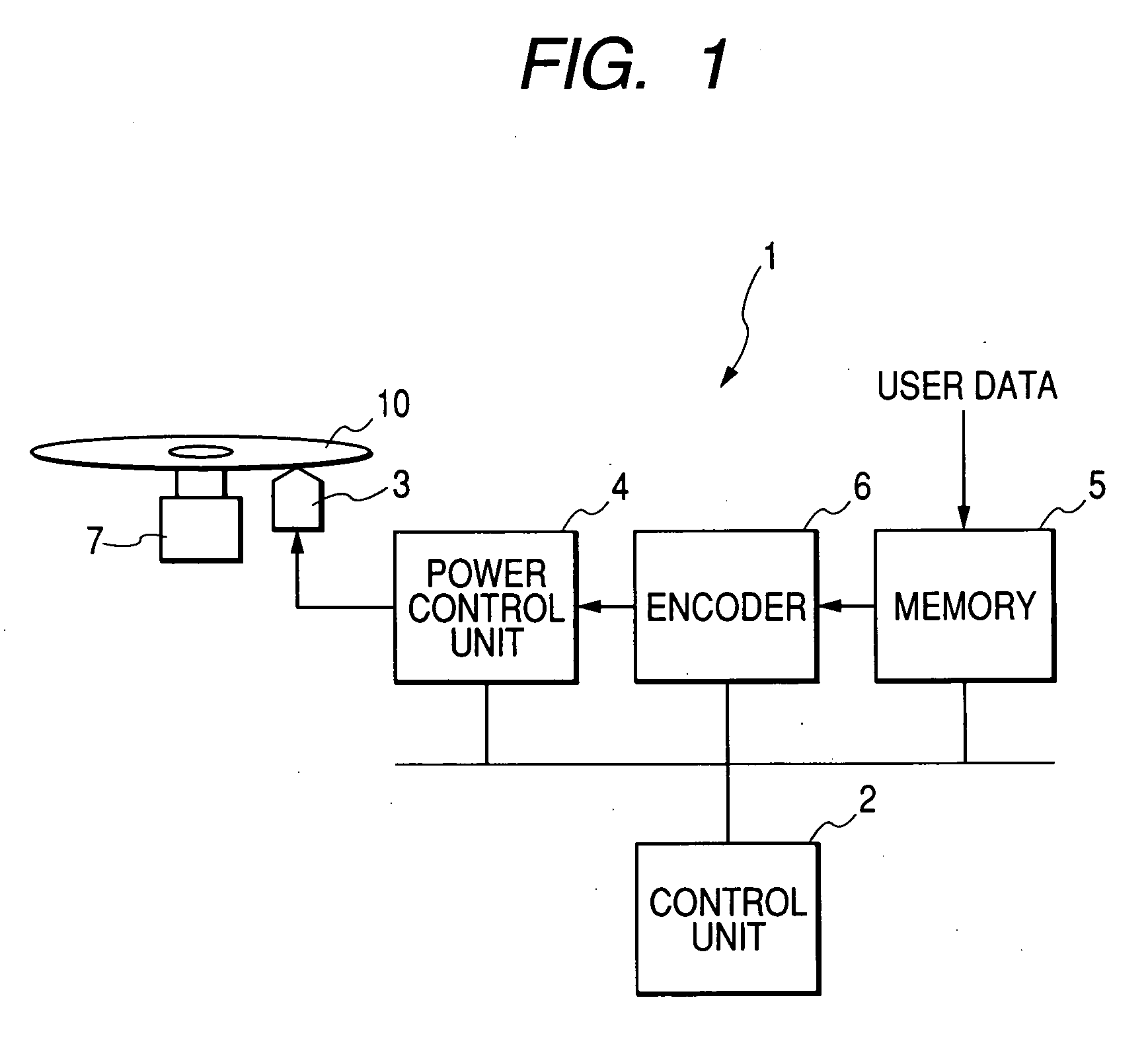
[0024]FIG. 1 is a view showing the configuration of the main part of the optical disk device which is the embodiment of this invention. An optical disk device 1 according to this embodiment includes a control unit 2 for controlling the operation of a device body, a pick-up head 3 for irradiating laser light on an optical disk 10 set in the device body, a power control unit 4 for controlling the power of the laser light to be irradiated onto the optical disk 10 from a pick-up head 3, a memory 5 serving as a buffer memory for temporarily holding the data to be recorded on the optical disk, and an encoder 6 for encoding the data stored in the memory. Incidentally, reference numeral 7 denotes a spindle motor for rotating the optical disk 10.

[0025] The pick-up head 3, as well known, includes an LD (laser diode), a PD (photo-diode), an objective lens, etc. The power control ...


PUM

PropertyMeasurementUnit
recording poweraaaaaaaaaa
poweraaaaaaaaaa
widthaaaaaaaaaa

Abstract

An optical disk device includes a recording power acquiring unit which acquires recording power, a recording unit which records data on an optical disk set in a device body by irradiating laser light of the recording power onto the optical disk, and a laser power control unit which controls power of the laser light. Preferably, the recording power is suited to record data on the optical disk, and the laser power control unit gradually decreases the power of the laser light irradiated in a linking region from the recording power based on a first prescribed condition when recording of data by the recording unit is ended and gradually increases the power of the laser light irradiated in the linking region to the recording power based on a second prescribed condition when the recording of data by the recording unit is started.

Description

BACKGROUND OF THE INVENTION [0001] 1. Field of the Invention [0002] This invention relates to an optical disk device for recording data on a write-once-read-many (WORM) type or rewritable type of optical disk such as DVD-R / RW and CD-R / RW. [0003] 2. Description of the Related Art [0004] Conventionally, optical disk devices for recording data (hereinafter referred to user data) on a write-once-read-many type or rewritable type of optical disk such as DVD-R / RW and CD-R / RW have commonly spread. The WORM type optical disk is capable of recording only once the user data. The rewritable type optical disk is capable of recording the user data repeatedly many times. The optical disk device, when it records the user data on the optical disk set in a device body, performs OPC (Optimize Power Control) prior to recoding of the user data to acquire power of laser light (hereinafter referred to as recording power) optimum to the recording of the user data. The OPC, as well known, refers to process...

Claims


Application Information

Patent Timeline
Patent Type & Authority Applications(United States)
IPC IPC(8): G11B7/0045G11B7/125G11B7/126
CPCG11B7/006G11B7/00736G11B7/126G11B2220/2537G11B2020/10898G11B2020/1277G11B2220/216G11B20/10
Inventor TSUKADA, SEIJI
Owner FUNAI ELECTRIC CO LTD
Learn More