
Methods and systems for patient airway and leak flow estimation for non-invasive ventilation

a leakage and patient technology, applied in the direction of respiratory masks, medical devices, other medical devices, etc., can solve the problems of significant risks, tissue abrasion, infection, sedation of patients, and significant problems with sensors, etc., to achieve the effect of reducing the risk of infection

Active Publication Date: 2022-07-19
KONINKLJIJKE PHILIPS NV
View PDF18 Cites 1 Cited by
  • Summary
  • Abstract
  • Description
  • Claims
  • Application Information

AI Technical Summary

Benefits of technology

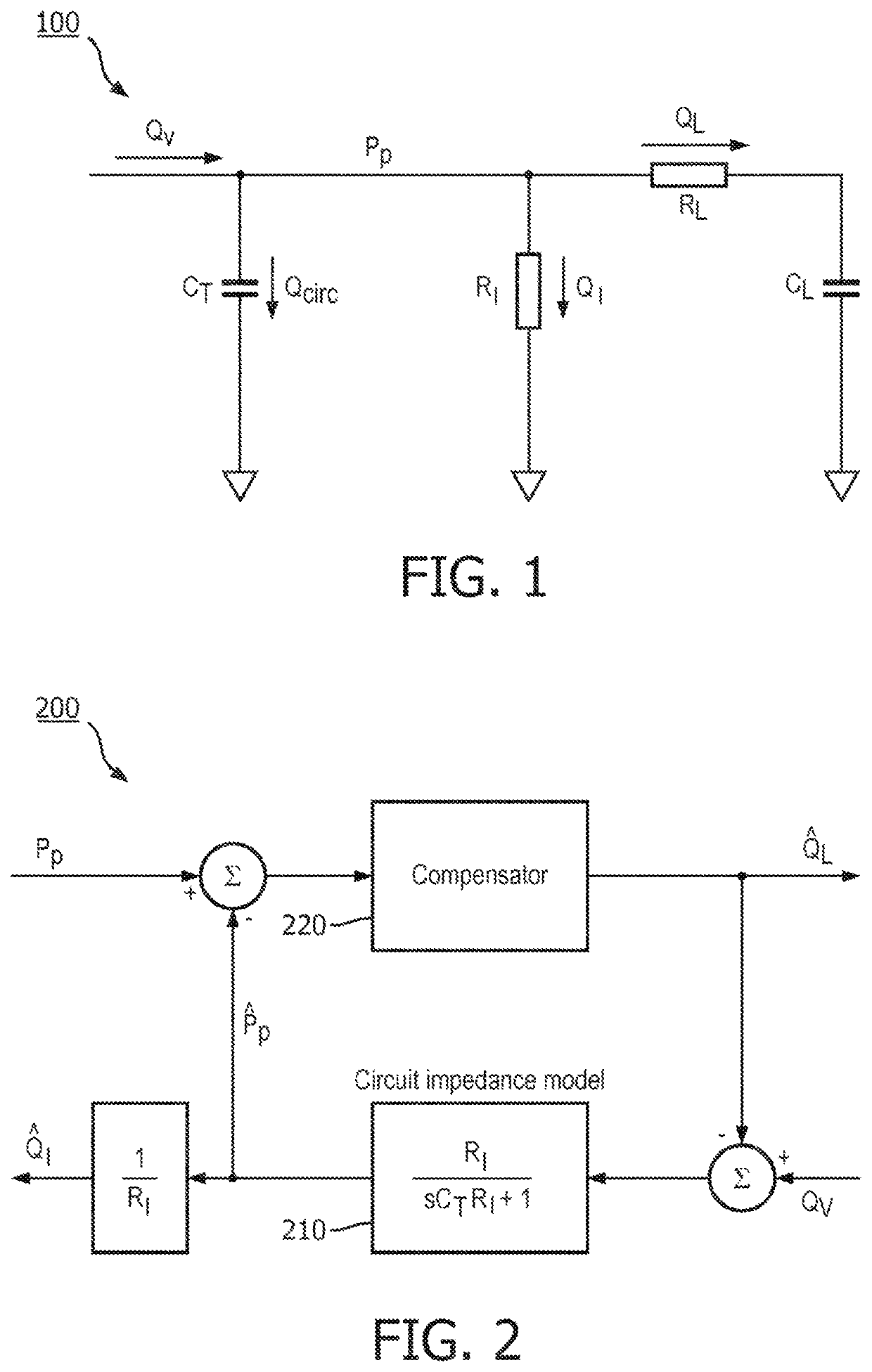
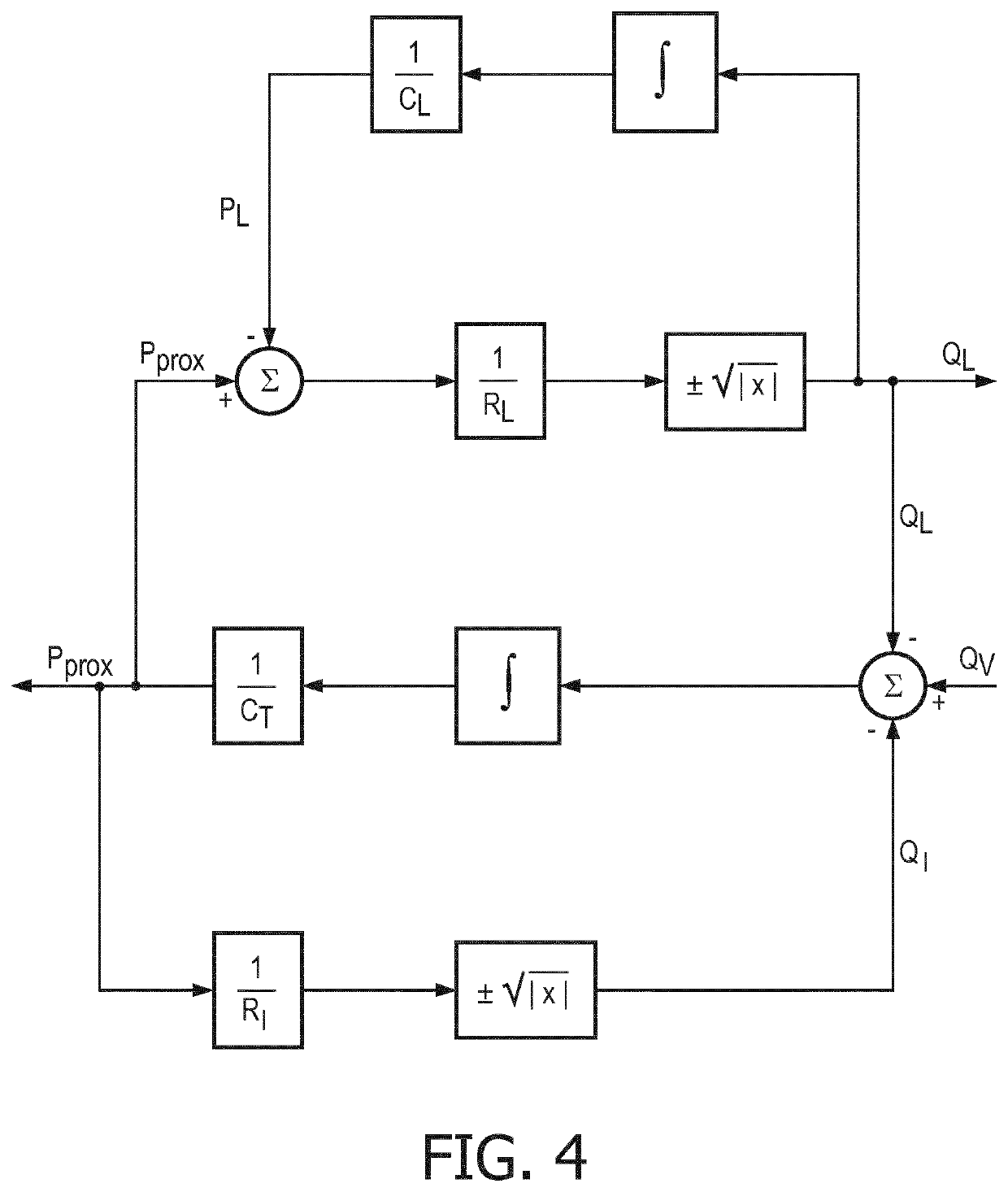
[0008]The present disclosure is directed to inventive methods and systems for estimating patient airway flow in a non-invasive ventilator system. Various embodiments and implementations herein are directed to a non-invasive ventilator system that calculates a highly accurate estimate of patient airway flow and of unknown leak flow. The non-invasive ventilator uses a feedback mechanism to minimize the difference between measured proximal pressure and estimated proximal pressure, where the estimated proximal pressure is generated using a model of the patient circuit that connects the ventilator with the patient. The non-invasive ventilator also compensates for leaks that can occur in the system by adjusting a known leak flow estimate.

Problems solved by technology

Intubation offers the best means of clinically managing the airway and maintaining lung inflation, but it introduce significant risks including tissue abrasion, infection, and sedation of the patient due to extreme discomfort.
However, the four to six feet of tubing that separate the ventilator and patient create significant issues with these sensors.
Tubing resistance and compliance tend to smooth flow transient, and leak leads to loss of flow at the patient's airway.
As a result, flow at the ventilator is a poor estimate of airway flow.
These models typically call for the differentiation of the measured pressure, which tends to amplify high frequency noise in the pressure input signal.
And since these filters do not involve lung mechanics, the model is incomplete and the airway flow estimate is even more inaccurate.

Method used


Image

  • Methods and systems for patient airway and leak flow estimation for non-invasive ventilation
  • Methods and systems for patient airway and leak flow estimation for non-invasive ventilation
  • Methods and systems for patient airway and leak flow estimation for non-invasive ventilation

Examples


example

Integration of Estimated Airway Flow and Determination of the Airway Flow Bias Metric

[0104]According to an embodiment, the following obtains the net breath volume:

[0105]VL⁢⁢inst⁡(n)={0.001if⁢⁢(StartOfInh⁡(n-1)==1)⁢⁢OR(QLreset==1)⁢⁢OR⁢⁢(fast⁢(n)==1)Δ⁢⁢T⁢Q^LNIV⁡(n)60+VL⁢⁢inst⁡(n-1)otherwise(26)

This says that the net breath volume calculation is reset one step after the start of inhalation (a one clock event) or otherwise held in reset during a fast bias correction maneuver. And the net volume is latched at the start of inhalation:

VL(k)=VL inst(n) if StartOfInh(n)==1  (27)

From the net breath volume obtain the mean breath flow by dividing net breath volume by the breath duration:

[0106]Q_L⁡(k)=VL⁡(k)TB⁡(k)(28)

next determine the mean (actual) breath pressure:

[0107]Σ⁢⁢Pprox⁢⁢Inst⁡(n)={0.001if⁢⁢(StartOfInh⁡(n-1)==1)⁢⁢OR(QLreset==1)⁢⁢OR⁢⁢(fast⁢(n)==1)Δ⁢⁢TPprox⁡(n)+Σ⁢⁢Pprox⁢⁢Inst⁡(n-1)otherwise⁢(29)⁢Σ⁢⁢Pprox⁡(k)=Σ⁢⁢Pprox⁢⁢Inst⁡(n)if⁢⁢StartOfInh⁡(n)==1(30)

and the average pressure over the brea...


PUM


Abstract

A method (800) for estimating patient airway flow in a non-invasive ventilator system includes: (i) determining (830) an estimated gas flow; (ii) determining (840) a proximal pressure error value; (iii) compensating (850) for the determined proximal pressure estimate error value; (iv) compensating (854) for an error in the estimated gas flow; (v) determining (856) an estimated gas flow leak; (vi) monitoring (860) on a breath to breath basis for a leak; (vii) determining (870) a gas flow leak factor; (viii) adjusting (880) the estimated gas flow leak; (ix) detecting (872) a bias on the airway flow estimate; (x) determining (874) that the system is within a quiescent state of a breath; (xi) de -biasing (976) the estimated gas flow to drive the bias to near zero; and (xii) suspending (878) breath to breath bias correction on an immediately subsequent breath.

Description

CROSS-REFERENCE TO PRIOR APPLICATIONS[0001]This application is the U.S. National Phase application under 35 U.S.C. § 371 of International Application No. PCT / EP2017 / 072979, filed on Sep. 13, 2017, which claims the benefit of U.S. Provisional Patent Application No. 62 / 396,427, filed on Sep. 19, 2017. These applications are hereby incorporated by reference herein.FIELD OF THE INVENTION[0002]The present disclosure is directed generally to methods and systems for estimating patient airway flow and leak flow utilizing remote ventilator pressure and flow sensors in a non-invasive ventilator system.BACKGROUND[0003]The most common means of providing critical care ventilation requires intubating patients with an endotracheal tube that seals within the trachea using an inflatable cuff. Intubation offers the best means of clinically managing the airway and maintaining lung inflation, but it introduce significant risks including tissue abrasion, infection, and sedation of the patient due to ext...

Claims


Application Information

Patent Timeline
Patent Type & Authority Patents(United States)
IPC IPC(8): A61M16/00A61M16/06
CPCA61M16/026A61M16/0051A61M16/0066A61M16/06A61M2016/0027A61M2016/0039A61M2205/15A61M2205/3331A61M2205/50
Inventor BORRELLO, MICHAEL ANTHONY
Owner KONINKLJIJKE PHILIPS NV
Learn More