Ultrasound diagnostic apparatus

Inactive Publication Date: 2009-02-05
NAT INST OF ADVANCED IND SCI & TECH
View PDF2 Cites 20 Cited by
  • Summary
  • Abstract
  • Description
  • Claims
  • Application Information

AI Technical Summary

Benefits of technology

[0024]According to the ultrasound diagnostic apparatus as claimed in claim 1, pressure distribution on the surface of an ultrasonic probe can be measured directly, thereby allowing the obtaining of highly reliable values. In addition, the use of sheet-like piezoelectric sensors enables the piezoelectric sensors to be composed with adequate thinness to a degree that does not have an effect on ultrasonic wave measurement.
[0025]According to the ultrasound diagnostic apparatus as claimed in claim 2, since the piezoelectric sensors can be made to have superior heat resistance, the piezoelectric sensors have sensitivity characteristics with extremely low temperature dependency, thereby eliminating the need for superfluous correction circuits.
[0034]According to the ultrasound diagnostic apparatus as claimed in claim 11, a location of a fluctuation site within a specimen can be estimated without being affected by the manner in which the ultrasonic probe is pressed against the specimen or local pressure changes within the contact surface.
[0035]According to the ultrasound diagnostic apparatus as claimed in claim 12, a location of a fluctuation site within an ultrasound tomographic image can be estimated easily.
[0036]According to the ultrasound diagnostic apparatus as claimed in claim 13, the extraordinary effect is obtained in which a location of a fluctuation site within an ultrasound tomographic image can be estimated.
[0037]According to the ultrasound diagnostic apparatus as claimed in claim 14, a value of elasticity, viscosity or inertia of each tissue layer composing a specimen can be estimated. In addition, since the use of a plurality of piezoelectric sensors allows the acquisition of pressure distribution within a contact surface, pressure distribution within a contact surface can be estimated in greater detail. Moreover, the use of sheet-like piezoelectric sensors enables highly accurate estimates to be made without being affected by ultrasonic wave information.

Problems solved by technology

In addition, pressure distribution on the surface of the ultrasonic probe is not uniform depending on the specimen.
Moreover, pressure acting on the surface of the ultrasonic probe is also affected by the manner in which the ultrasonic probe is pressed against a specimen.

Method used


Image

  • Ultrasound diagnostic apparatus
  • Ultrasound diagnostic apparatus
  • Ultrasound diagnostic apparatus

Examples


Embodiment Construction

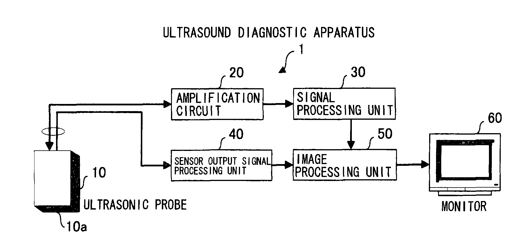
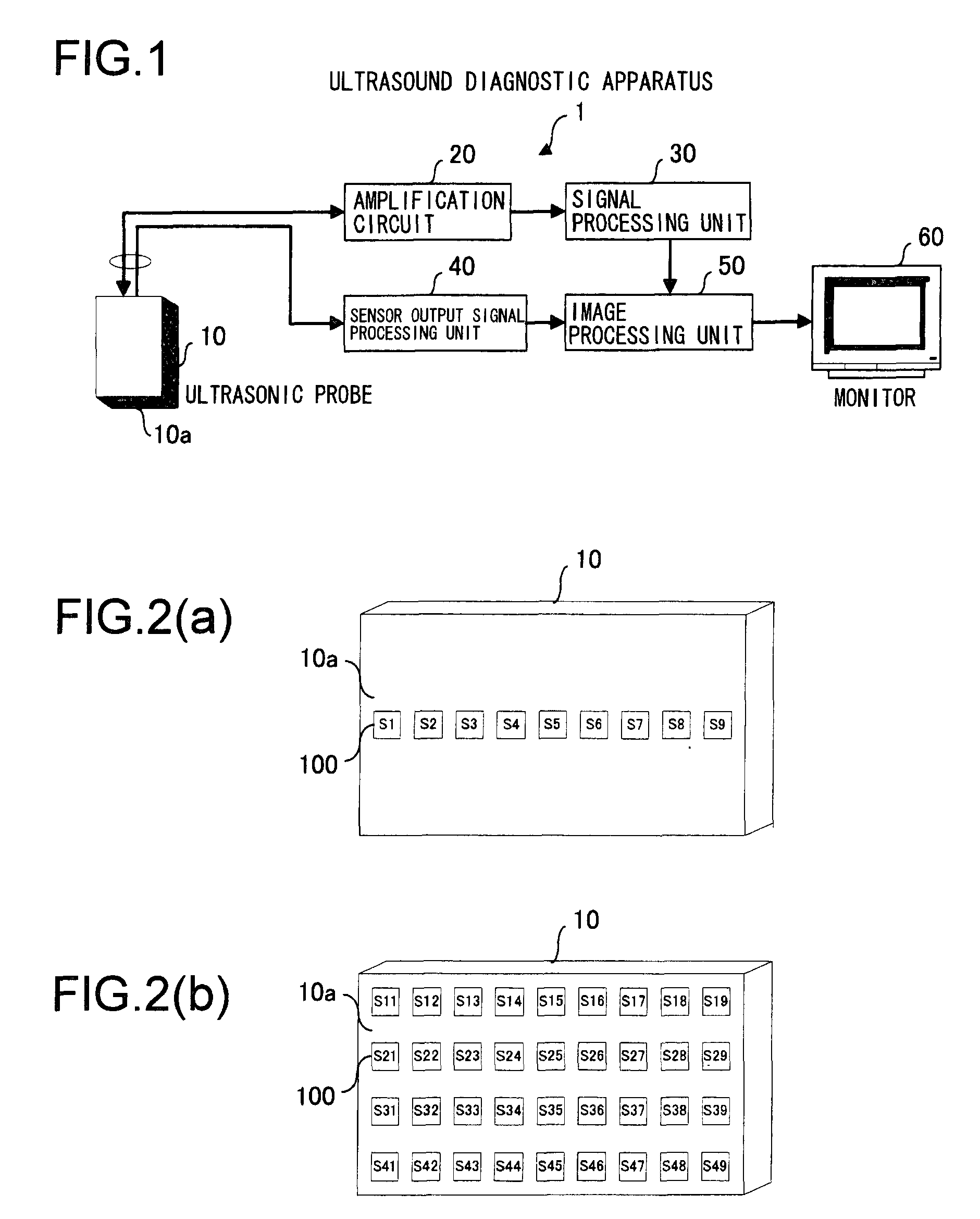
[0069]The following provides an explanation of embodiments of the ultrasound diagnostic apparatus of the present invention in accordance with the drawings. FIG. 1 is a block diagram showing an example of the configuration of an ultrasound diagnostic apparatus 1 of the present invention. The basic configuration of the ultrasound diagnostic apparatus 1 consists of an ultrasonic probe 10, an amplification circuit 20, a signal processing unit 30, a sensor output signal processing unit 40, an image processing unit 50 and a monitor 60.

[0070]Piezoelectric sensors 100 as shown in FIG. 2 are arranged on a surface 10a of ultrasonic probe 10 that contacts a specimen. In addition, a large number of ultrasonic oscillators are arranged within ultrasonic probe 10, and each ultrasonic oscillator has a function for generating an electrical signal from amplification circuit 20 after converting to ultrasonic waves, and a function for receiving ultrasonic waves reflected from a specimen and outputting ...


PUM


Abstract

Pressure distribution on a surface of an ultrasonic probe can be measured directly. Piezoelectric sensors, in which a piezoelectric thin film is formed on a film-like substrate, are arranged in the form of an array on the surface of an ultrasonic probe, and a sensor output signal processing unit outputs pressure measured for each piezoelectric sensor S1, S2 to S9 based on output signals from each of the piezoelectric sensors to an image processing unit. The image processing unit generates a histogram of the measured pressures for piezoelectric sensors S1, S2 to S9, and displays the histogram, while plotting the piezoelectric sensors on the x axis and the measured pressures on the Y axis, along with the resulting ultrasound tomographic image, on a monitor.

Description

TECHNICAL FIELD[0001]The present invention relates to an ultrasound diagnostic apparatus which is provided with an ultrasonic probe that contacts a specimen, and which generates an ultrasound tomographic image by transmission and reception of ultrasonic waves through the ultrasonic probe, and more particularly, to an ultrasound diagnostic apparatus that measures pressure distribution on the surface of an ultrasonic probe.BACKGROUND[0002]Numerous ultrasound diagnostic apparatuses have been developed in the past that generate ultrasound tomographic images of the interior of a specimen by utilizing ultrasonic waves output from an ultrasonic probe. In addition, such ultrasound diagnostic apparatuses employ technologies for acquiring pressure data generated on the surface of the interior of a specimen. For example, according to the technology described in Patent Document 1, pressure applied to a specimen is calculated from the movement distance of an ultrasonic probe and the contact surf...

Claims


Application Information

Patent Timeline
IPC IPC(8): A61B8/14
CPCA61B8/14A61B8/4281A61B8/485G01S15/899A61B2562/046B06B1/0629A61B2562/0247
Inventor FUKUDA, OSAMUUENO, NAOHIROTSUBAI, MASAYOSHIAKIYAMA, MORITO
Owner NAT INST OF ADVANCED IND SCI & TECH
Why Eureka
Try Eureka