
Method and systems for patient airway and leak flow estimation for non-invasive ventilation

a leakage and patient technology, applied in the field of patient airway and leakage estimation for non-invasive ventilation, can solve the problems of tissue abrasion, infection, sedation of patients, significant problems with sensors, etc., and achieve the effect of high-quality estimate of patient airway flow

Active Publication Date: 2018-07-19
KONINKLJIJKE PHILIPS NV
View PDF34 Cites 3 Cited by
  • Summary
  • Abstract
  • Description
  • Claims
  • Application Information

AI Technical Summary

Benefits of technology

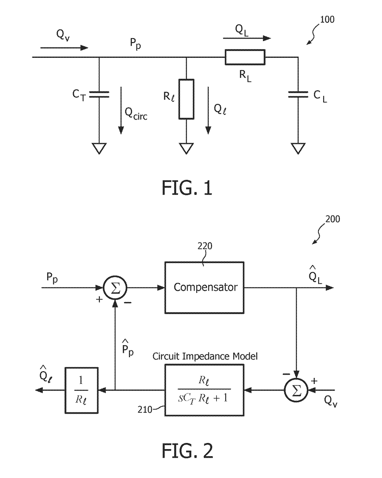
The present patent is about methods and systems for estimating the flow of air in a patient's airway during ventilation with a non-invasive ventilator. The ventilator uses a feedback mechanism to minimize the difference between measured pressure and estimated pressure, generated using a model of the patient's airway. The ventilator also compensates for leaks in the system by adjusting the estimated leak flow. The technical effects include accurate airway flow estimation and effective compensation for leaks.

Problems solved by technology

Intubation offers the best means of clinically managing the airway and maintaining lung inflation, but it introduce significant risks including tissue abrasion, infection, and sedation of the patient due to extreme discomfort.
However, the four to six feet of tubing that separate the ventilator and patient create significant issues with these sensors.
Tubing resistance and compliance tend to smooth flow transient, and leak leads to loss of flow at the patient's airway.
As a result, flow at the ventilator is a poor estimate of airway flow.
These models typically call for the differentiation of the measured pressure, which tends to amplify high frequency noise in the pressure input signal.
And since these filters do not involve lung mechanics, the model is incomplete and the airway flow estimate is even more inaccurate.

Method used


Image

  • Method and systems for patient airway and leak flow estimation for non-invasive ventilation
  • Method and systems for patient airway and leak flow estimation for non-invasive ventilation
  • Method and systems for patient airway and leak flow estimation for non-invasive ventilation

Examples


Embodiment Construction

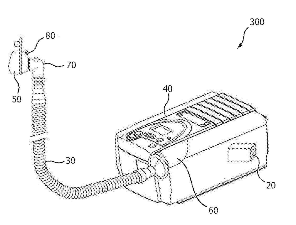
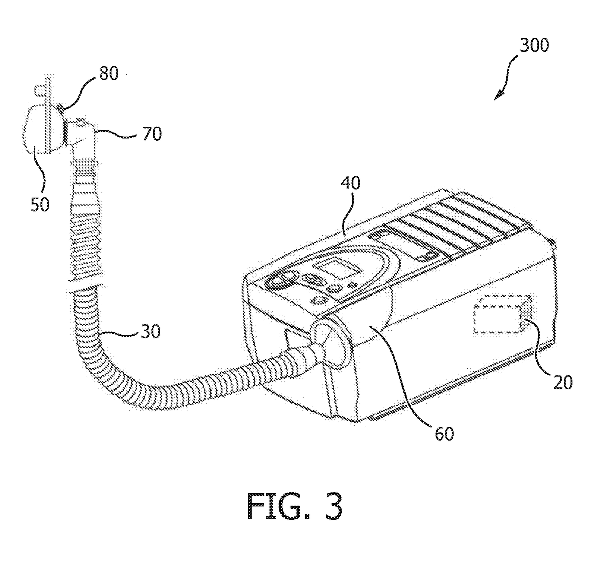
[0029]The present disclosure describes various embodiments of a non-invasive ventilator (“NIV”) system and method. More generally, Applicants have recognized and appreciated that it would be beneficial to provide an NIV that accurately estimates patient airway flow and leak flow utilizing remote ventilator pressure and flow sensors. For example, the NIV uses feedback control to minimize the difference between measured and estimated proximal pressure, where the estimated pressure is synthesized using a model of the patient circuit that connects the ventilator with the patient. Unexpected or unknown leaks that occur during use are compensated using a feedback mechanism that modifies net flow to zero by adjusting a known leak estimate. The method and system results in an airway flow estimate that closely tracks true airway flow with low noise and minimum bias, and provides an accurate estimate of the unknown leak flow.

[0030]Although the method and system described below is applied to a...


PUM


Abstract

A method (600) for estimating patient airway flow in a non-invasive ventilator system. The method includes the steps of: (i) determining (630) an estimated gas flow at the proximal end of the tubing; (ii) determining (640) a proximal pressure error value by subtracting the measured pressure at the proximal end of the tubing from the estimated pressure at the proximal end of the tubing; (iii) compensating for the determined proximal pressure estimate error value; (iv) compensating (654) for an error in the estimated gas flow at the proximal end of the tubing by feeding the estimate back into a sum of accumulated flows; (v) determining (656) an estimated gas flow leak; (vi) monitoring (660) for a leak in the non-invasive ventilator system; (vii) determining (670) a gas flow leak factor; (viii) adjusting (680) the estimated gas flow leak; and (ix) compensating (690) for bias in the patient airway flow.

Description

FIELD OF THE INVENTION[0001]The present disclosure is directed generally to methods and systems for estimating patient airway flow and leak flow utilizing remote ventilator pressure and flow sensors in a non-invasive ventilator system.BACKGROUND[0002]The most common means of providing critical care ventilation requires intubating patients with an endotracheal tube that seals within the trachea using an inflatable cuff. Intubation offers the best means of clinically managing the airway and maintaining lung inflation, but it introduce significant risks including tissue abrasion, infection, and sedation of the patient due to extreme discomfort. Accordingly, intubation is appropriately called ‘invasive’ ventilation, and the clinician's decision to intubate must be carefully considered. For a select group of hospitalized patients requiring breathing support, the risks leading to adverse side effects of intubation can outweigh the benefits.[0003]In light of significant risks of invasive v...

Claims


Application Information

Patent Timeline
Patent Type & Authority Applications(United States)
IPC IPC(8): A61M16/00A61M16/06A61M16/08
CPCA61M16/026A61M16/0003A61M16/0051A61M16/0057A61M16/06A61M16/0875A61M2016/0036A61M2205/15A61M2205/18A61M2205/3334A61M2230/40A61M11/00
Inventor BORRELLO, MICHAEL ANTHONY
Owner KONINKLJIJKE PHILIPS NV
Learn More