
Sucktion cup

a suction cup and cup body technology, applied in the field of suction cups, can solve the problems of insufficient suction force falling of the suction cup, and reduced suction force, so as to prevent elastic fatigue and stably attach to the surface of the obj

Active Publication Date: 2022-07-19
FREE FREEUSA INC +1
View PDF10 Cites 1 Cited by
  • Summary
  • Abstract
  • Description
  • Claims
  • Application Information

AI Technical Summary

Benefits of technology

[0006]The technical effect of the present invention is to use the insertion pin for securing the suction cup member in order to maintain the vacuum space such that it is able to prevent elastic fatigue that may cause the falling of the suction cup member. Consequently, the suction cup of the present invention is able to stably attach onto an object surface.

Problems solved by technology

Nevertheless, known suction cups are found to have defects, and the main cause of such defects is due to the excessive softness of suction cup or existence of gap allowing external air to enter into the inner side of the suction cup such that the suction force of the suction cup is insufficient, leading to falling of the suction cup.
Known suction cup typically uses an elastic material, and after a long term of use, elastic fatigue is likely to occur such that gap is generated and air is able to penetrate into the internal of the cup, causing the suction force to reduce.
As a result, the suction cup cannot be stably attached onto the wall or any flat surface, and the object hung on the wall with the suction cup also falls, leading to damage of object.

Method used


Image

  • Sucktion cup
  • Sucktion cup
  • Sucktion cup

Examples


Embodiment Construction

[0014]The following provides detailed description on the exemplary embodiments of the present invention along with the accompanied drawings.

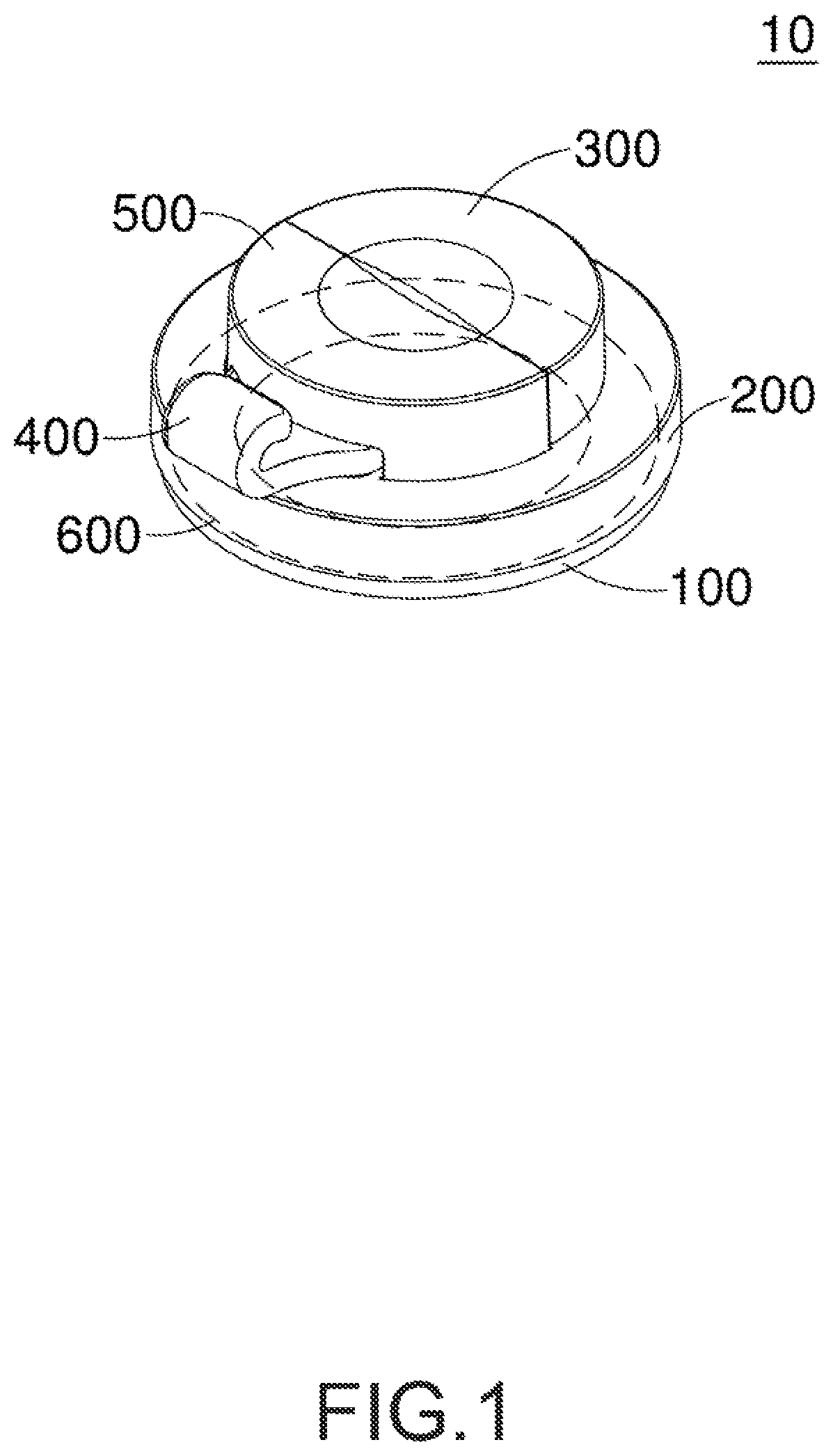
[0015]FIG. 1 shows a perspective view of a suction cup according to an exemplary embodiment of the present invention. As shown in the drawing, according to an exemplary embodiment of the present invention, a suction cup 10 comprises a suction cup member 100, a press ring 600, a first housing 200 and an insertion pin 300.

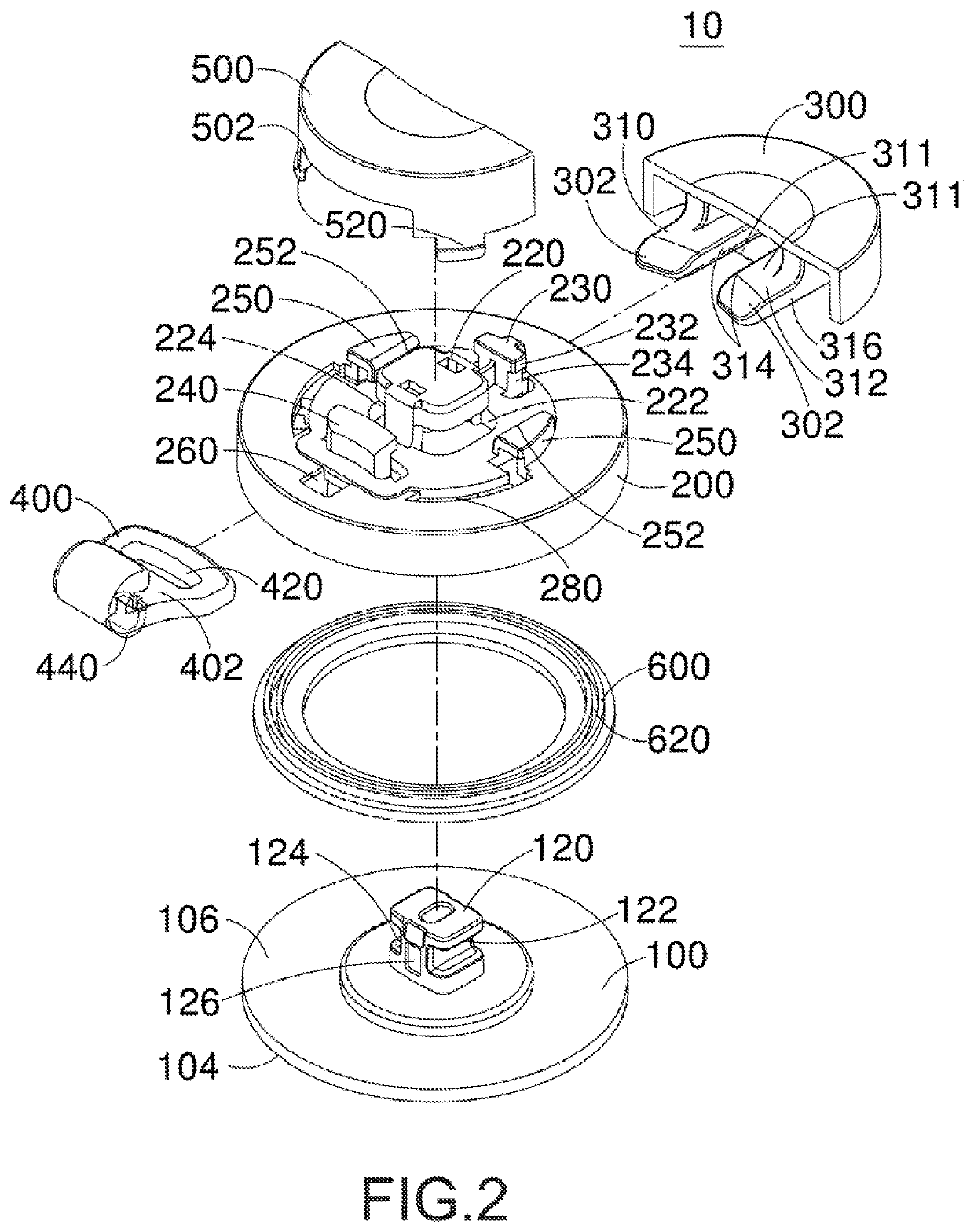
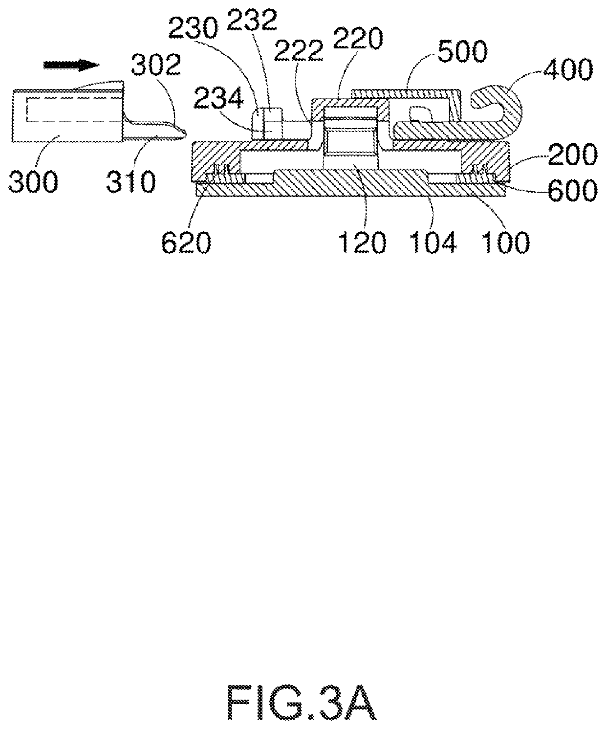
[0016]FIG. 2 shows an exploded view of the suction cup according to an exemplary embodiment of the present invention. As shown in the drawing, the suction cup member 100 includes a suction surface 104 at a lower portion thereof and an assembly surface at an upper portion of the suction cup member 100. The assembly surface 106 includes a first protrusion 120 arranged on a top portion thereof, and one side of the first protrusion 120 further includes a first cut-out slot 122 formed thereon. The press ring 600 is pressed onto a top ...


PUM


Abstract

A suction cup comprises a suction cup member, a press ring, a first housing and an insertion pin. The suction cup member includes an assembly surface and a suction surface. The assembly surface includes a first protrusion having a first cut-out slot formed thereon. The press ring is pressed onto an upper outer edge of the suction cup member. The first housing is pressed onto the press ring and includes a second protrusion for mounting onto the first protrusion. One side of the second protrusion includes a first through hole corresponding to the first cut-out slot to expose the first cut-out slot. The insertion pin partially engages with the first housing and slidably engages with the first through hole and the first cut-out slot to move in the first cut-out slot and to drive the suction cup member to move upward while forming a vacuum space underneath thereof simultaneously.

Description

CROSS-REFERENCE TO RELATED APPLICATIONS[0001]This application is the National Phase of PCT International Application No. PCT / US2018 / 057535 filed on Oct. 25, 2018. The entire disclosure of the above application is all incorporated herein by reference.BACKGROUND OF THE INVENTIONField of the Invention[0002]The technical field relates to a suction cup, in particular, to the structure of a suction cup using an insertion pin for lifting the suction cup.Description of Related Art[0003]Presently, suction cups have become one of the products commonly used in households and our daily lives, and they mainly utilize vacuum for attaching onto wall surfaces or any flat surfaces. Typically, a suction cup is provided with a hook extended therefrom, and the hook can provide the function for object hanging. Nevertheless, known suction cups are found to have defects, and the main cause of such defects is due to the excessive softness of suction cup or existence of gap allowing external air to enter in...

Claims


Application Information

Patent Timeline
Patent Type & Authority Patents(United States)
IPC IPC(8): F16B47/00F16B21/09
CPCF16B47/00F16B21/09F16B45/00
Inventor LIU, SHENG-YU
Owner FREE FREEUSA INC
Learn More