
Tube connector

a technology of tube connectors and connectors, applied in the direction of fluid pressure sealing joints, couplings, mechanical instruments, etc., can solve the problems of weakening of the sealing between the tube connectors, too high cost, and complicated structure, so as to avoid elastic fatigue of the sealing ring and enhance the fixing ability

Active Publication Date: 2022-10-04
KUO HSIN CHENG +1
View PDF17 Cites 0 Cited by
  • Summary
  • Abstract
  • Description
  • Claims
  • Application Information

AI Technical Summary

Benefits of technology

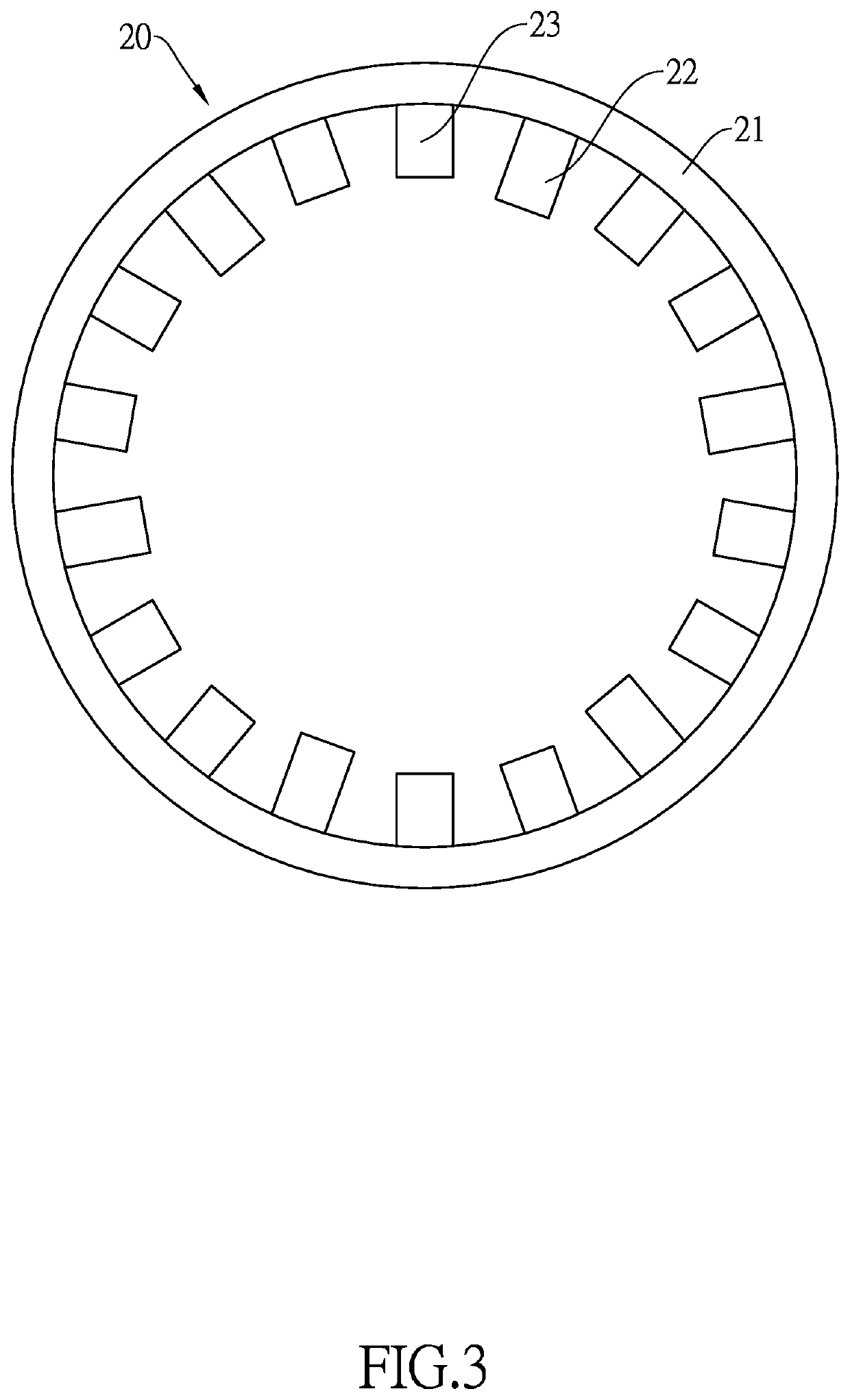
The present invention provides a tube connector with an altered inner annular space that accommodates a restricting element and a sealing ring. The restricting element has multiple first and second restricting teeth of different lengths, which enhances the fixing ability of the tube body. The sealing ring and restricting element abut each other to maintain sealing, and changes in pressure from fluid transporting in the tube body move the tube body and main body relative to each other, keeping the sealing ring elastic and avoiding fatigue. The restricting element has multiple teeth of different lengths, which allows for enhanced sealing and increased or decreased abutting force of the sealing ring to maintain its elasticity. The restricting element is composed of less components, making it cost-effective and easy to assemble with the tube body.

Problems solved by technology

As a result, after in use for a period of time, the sealing ring 51 may get elastic fatigue, which weakens the sealing between the tube connector and the tube body, and may cause leakage.
Lastly, the conventional tube connector is composed of too many components for installation with the tube body, such that the structure is too complicated and the cost is too high.

Method used


Image

  • Tube connector
  • Tube connector
  • Tube connector

Examples


first embodiment

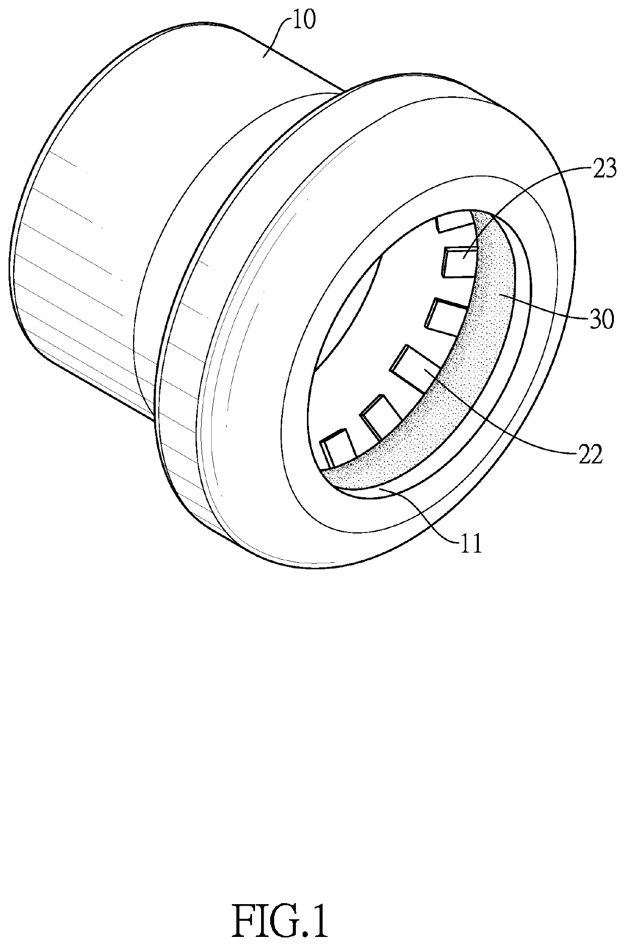
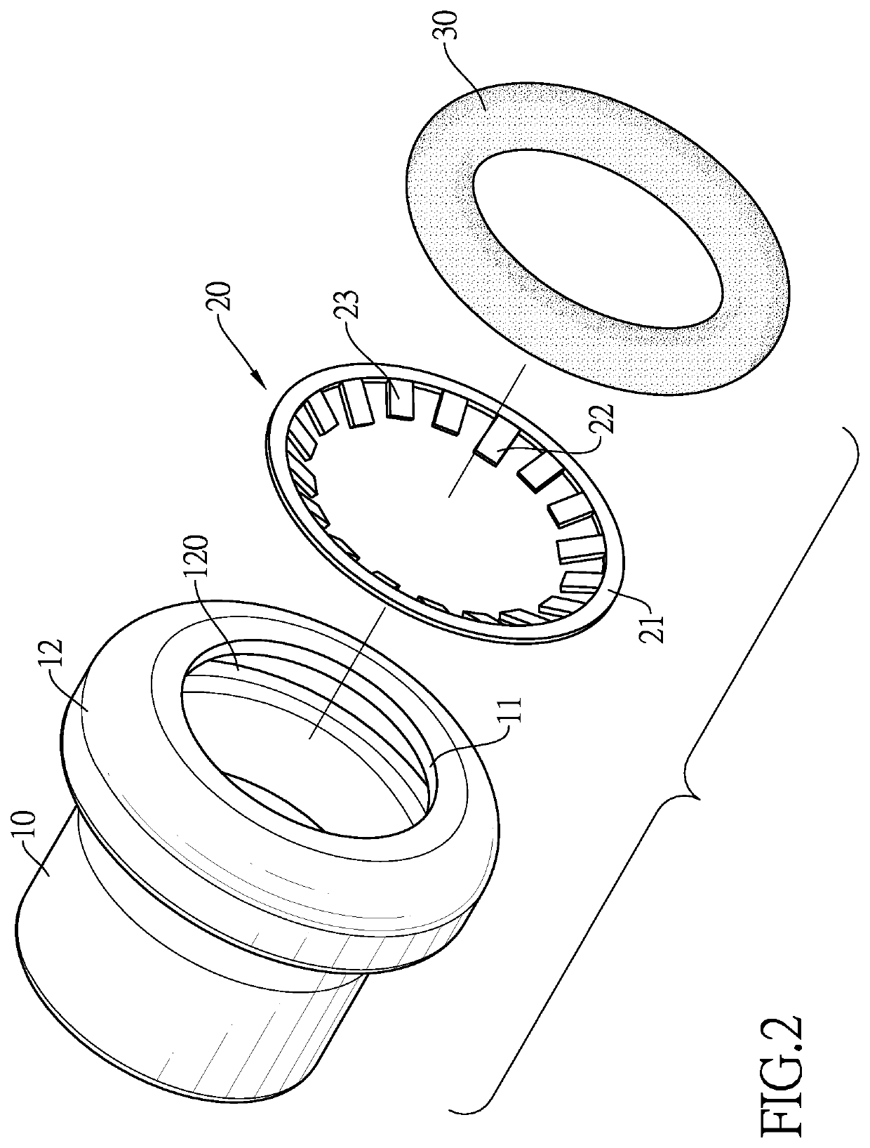
[0026]With reference to FIGS. 1 to 5, a tube connector in accordance with the present invention comprises a main body 10, a restricting element 20 and a sealing ring 30.

[0027]In a preferred embodiment, the main body 10 is hollow and has two ends opposite to each other. One of the two ends has an opening 11, and the other end is a sealing end. The main body 10 has a mounting segment 12 adjacent to the opening 11. The mounting segment 12 extends outwardly and transversely to form an inner annular space 120 inside of the mounting segment 12. The inner annular space 120 communicates with the opening 11 and an inner side of the main body 10. The inner annular space 120 has an annular surrounding wall, a first abutting surface 121, and a second abutting surface 122. The first abutting surface 121 and the second abutting surface 122 are connected to two sides of the annular surrounding wall respectively. Both the first abutting surface 121 and the second abutting surface 122 are annular. T...

second embodiment

[0038]When the second embodiment is in use, the two tube bodies 40A are respectively inserted into the two openings 11A, 110A to be inserted into the main body 10A. The two tube bodies 40A are respectively mounted through the two mounting segments 12A, and thus each of the tube bodies 40A is mounted through the sealing ring 30 and the restricting element 20 in the corresponding mounting segment 12A. The teeth of the restricting element 20 still can engage and position the tube body 40A.

[0039]The changing pressure of the fluid in the main body 10A and the tube body 40A still moves the main body 10A and tube body 40A relatively, and thus the sealing ring 30 is abutted tightly or slightly to and fro, thereby maintaining the elasticity of the sealing ring 30.

[0040]With reference to FIGS. 9 and 10, which show another embodiment of the restricting element 200, in this preferred embodiment, the restricting element 200 is similar to the abovementioned preferred embodiment but an amount of t...


PUM


Abstract

A tube connector has a main body, a restricting element, and a sealing ring. The main body has a mounting segment extending outwardly and transversely to form an inner annular space to accommodate the restricting element and the sealing ring. When the tube body is inserted, the tube body will be engaged and positioned by teeth of the restricting element. The sealing ring and the restricting element abut each other to maintain the sealing from the sealing ring. The changes of the pressure from the fluid transporting in the tube body will move the tube body and the main body relatively to and fro, and thus the abutting force against the sealing ring will increase or decrease accordingly, which maintains the elasticity of the sealing ring to maintain the sealing after a long time of use, thereby avoiding elastic fatigue and prolonging the lifespan.

Description

BACKGROUND OF THE INVENTION1. Field of the Invention[0001]The present invention relates to a tube connector that can connect two tube bodies or can seal an end of a tube body.2. Description of the Prior Arts[0002]A tube connector is used in a tube system for transferring fluid. In the tube system, multiple tube bodies are connected to each other or ends of some of the tube bodies are sealed depending on the tube design, and thus the fluid can flow in the tube system.[0003]With reference to FIG. 11, the tube connector has a hollow main body 50, which has at least one opening for mounting one single tube body or connecting two tube bodies. The main body 50 further has an annular seat 501 and a fixing segment 502 concaved in the opening. A sealing ring 51 is mounted in and abuts the annular seat 501. An abutting ring 55 is mounted in an assembling ring 54. A restricting element 53 is mounted in a sealing element 52. When the assembling element 54 is mounted in the fixing segment 502 of...

Claims


Application Information

Patent Timeline
Patent Type & Authority Patents(United States)
IPC IPC(8): F16L37/091F16L19/08F16L23/18
CPCF16L37/091F16L19/08F16L23/18F16L37/0845F16L13/142F16L37/092F16L55/00F16L17/02F16L21/02
Inventor KUO, HSIN CHENGKUO, HUNG CHENG
Owner KUO HSIN CHENG
Learn More