
Method for suppression of representations of reflections in at least one camera image of a camera of an environment sensor device of a motor vehicle and the corresponding environment sensor device

a technology of environment sensor and camera image, which is applied in the direction of camera filters, television systems, instruments, etc., can solve the problem of insufficient dynamic process of static orientation of polarization filter devices

Active Publication Date: 2022-08-23
AUDI AG
View PDF14 Cites 0 Cited by
  • Summary
  • Abstract
  • Description
  • Claims
  • Application Information

AI Technical Summary

Benefits of technology

[0006]The reflection of light on a reflective surface of an environment object generally produces polarized light. Thus, by the use of a polarization filter device, it is possible to suppress or dampen or reduce the light which belongs to a reflection or originates in a reflection by means of a polarization filter device when detecting a camera image. Hence, at least a dampened or no representation of the reflection will result in the camera image.
[0028]Thanks to the operation of the environment sensor device described herein, a method is produced. In other words, the method involves the suppression of representations of reflections (mirror images and / or highlights) in at least one camera image of a camera which is operated in an environment sensor device of a motor vehicle. The camera generates the at least one such camera image, in which an environment or a surrounding field of the motor vehicle is represented. A polarization filter device dampens the light entering the camera from the surrounding field with respect to a predetermined polarization direction, so that this light is only reproduced in dampened or reduced form in the at least one camera image. A processor device identifies at least one environment object in the at least one camera image. An estimator device now estimates a respective orientation of a respective surface normal of at least one surface in the at least one environment object. This may be done for one environment object or for more than one environment object. It may be done for one surface or for more than one surface of each environment object. An adjusting device determines, in dependence on the respective estimated orientation of the at least one surface, a respective target polarization direction of the polarization filter by which a respective representation of reflections on the respective surface is reduced in the at least one camera image. The adjusting device generates a control signal according to the respectively determined target polarization direction. The described selection for one environment object or several environment objects and for one surface or several surfaces can also be done, if the polarization filter device cannot adjust so many different polarization directions at the same time for different regions corresponding to the identified surfaces. The polarization filter then adjusts its polarization direction in dependence on the control signal.

Problems solved by technology

However, when detecting the at least one environment object on the basis of at least one camera image of a camera there may occur a false recognition, which means that a supposed environment object is detected, although this is merely a reflection in a reflecting surface of another environment object.
A static orientation of a polarization filter device is inadequate for dynamic processes, such as the monitoring of at least one environment object in the surrounding field of a motor vehicle.

Method used


Image

  • Method for suppression of representations of reflections in at least one camera image of a camera of an environment sensor device of a motor vehicle and the corresponding environment sensor device
  • Method for suppression of representations of reflections in at least one camera image of a camera of an environment sensor device of a motor vehicle and the corresponding environment sensor device
  • Method for suppression of representations of reflections in at least one camera image of a camera of an environment sensor device of a motor vehicle and the corresponding environment sensor device

Examples


Embodiment Construction

[0034]In the figures, the same reference numbers each time denote functionally identical elements.

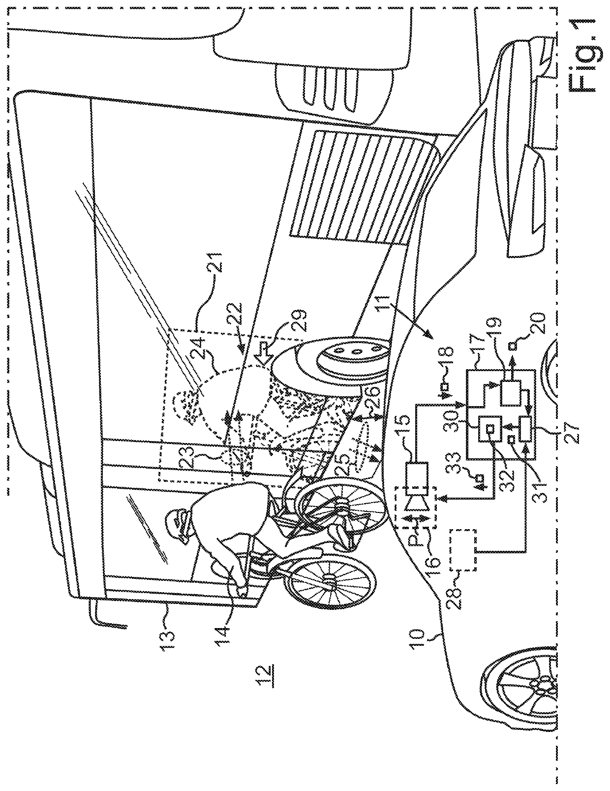
[0035]FIG. 1 shows a motor vehicle 10, which may be an automobile, especially a passenger car or a truck. The motor vehicle 10 may comprise an environment sensor device 11, by means of which an environment or a surrounding field 12 of the motor vehicle 10 can be detected in automated manner in the motor vehicle 10. In particular, at least one environment object 13, 14 can be detected and identified in the surrounding field 12 by means of the environment sensor device 11. FIG. 1 shows, for example, that the environment object 13 may be a minibus and the environment object 14 may be a bicyclist.

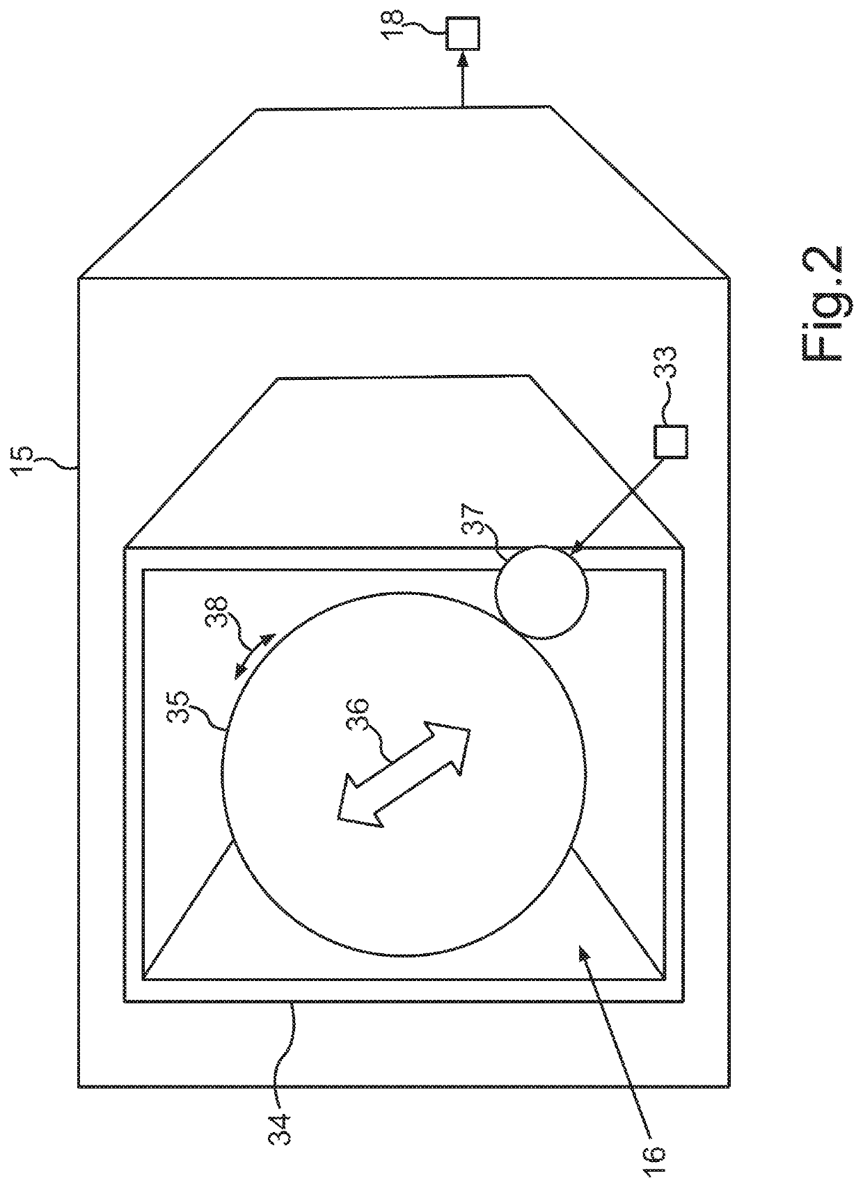
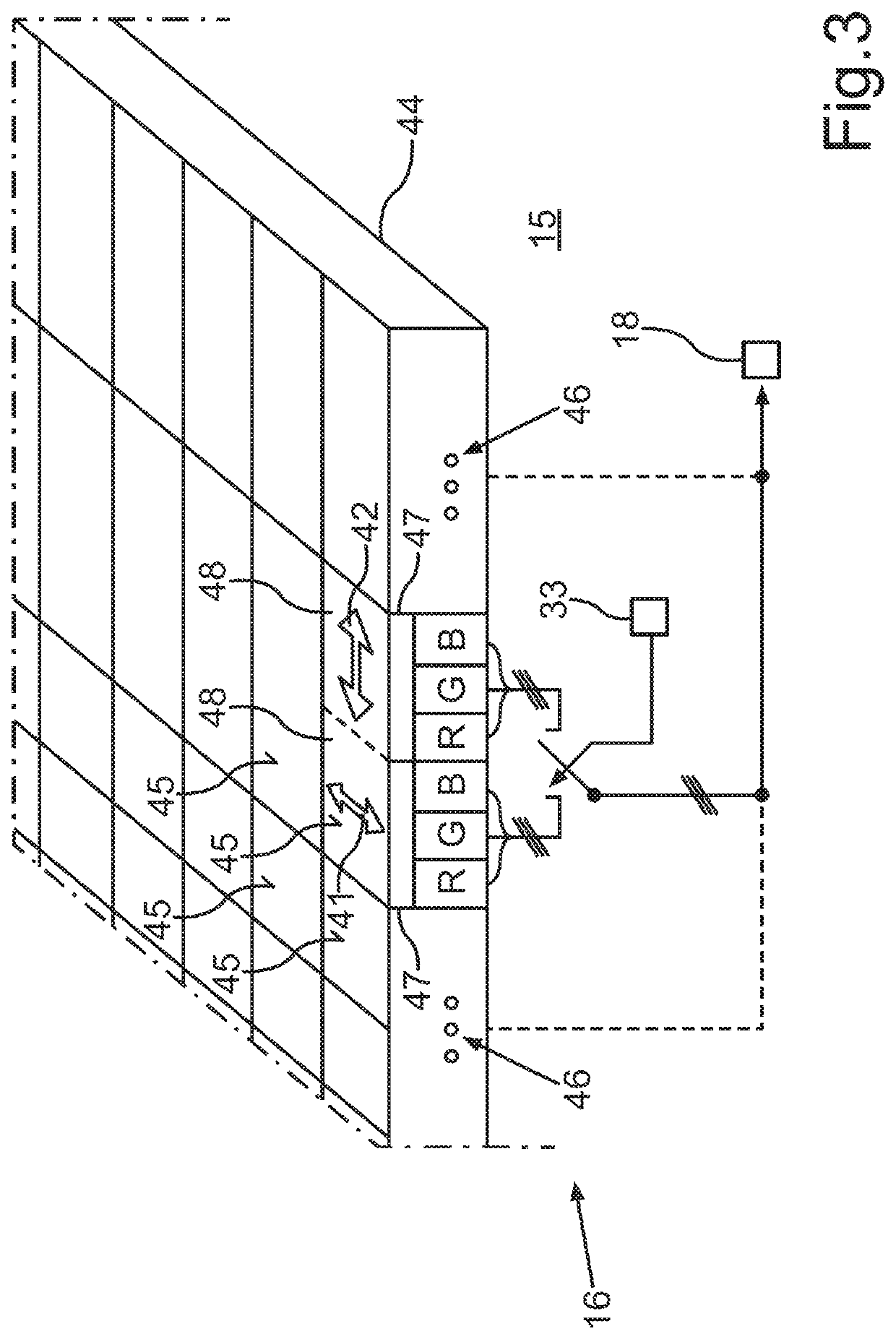
[0036]The environment sensor device 11 may comprise a camera 15, a polarization filter device 16 and a processor device 17. The camera 15 may be, for example, a color camera or an infrared camera or a grayscale camera or a combination of these camera types. The camera 15 may be a single-image camer...


PUM


Abstract

In a method for suppression of reflections in at least one camera image of a camera of a motor vehicle, the camera generates the at least one camera image and thereby a polarization filter device dampens light incident from a surrounding field in regard to a predetermined polarization direction. An estimator device estimates a respective orientation of a respective surface normal of at least one surface on at least one environment object and an adjusting device determines a respective target polarization direction for the polarization filter device in dependence on the respective estimated orientation of the at least one surface normal, by which a respective representation of reflections at the respective surface is reduced in the at least one camera image, and generates a control signal according to the respectively determined target polarization direction, and the polarization filter device adjusts its polarization direction in dependence on the control signal.

Description

BACKGROUNDTechnical Field[0001]Embodiments of the invention relate to an environment sensor device for a motor vehicle. The environment sensor device detects at least one environment object in a surrounding field of the motor vehicle by means of a camera. In order to not represent reflections which may be present on a surface of an environment object in the camera images of the camera, a polarization filter device is provided. Embodiments of the invention also include a motor vehicle having the environment sensor device as well as a method for the suppression of representations of said reflections in camera images.Description of the Related Art[0002]The use of a polarization filter device is known, for example, from DE 10 2014 017 229 A1. By means of the polarization filter device, those reflections are not represented in camera images of a camera that are visible in a windshield of the motor vehicle through which the camera is filming a surrounding field of the motor vehicle. The a...

Claims


Application Information

Patent Timeline
Patent Type & Authority Patents(United States)
IPC IPC(8): H04N5/238G02B27/28G06V10/60G06V20/58G08G1/16H04N5/225G03B11/00G03B15/00G06V10/145
CPCH04N5/238G02B27/281G06V10/60G06V20/58G08G1/166H04N5/2254G03B11/00G03B15/00G06V10/145H04N23/75H04N23/55
Inventor RAAIJMAKERS, MARVINKRÄMER, STEFAN
Owner AUDI AG
Learn More