
System and method for forming aligned holes in a work piece

a technology of aligned holes and workpieces, applied in the field of drill jigs, can solve the problems of insufficient accuracy and/or precision, low degree of accuracy and precision of drill stencils, and inability to provide sufficient accuracy and/or precision, etc., to achieve convenient quick and easy drilling of holes, reduce wear on the drill bit, and improve ergonomics for users

Active Publication Date: 2022-10-11
DEGOWSKE ROBERT JAMES
View PDF7 Cites 1 Cited by
  • Summary
  • Abstract
  • Description
  • Claims
  • Application Information

AI Technical Summary

Benefits of technology

The drill jig system enables quick, precise, and consistent drilling of multiple holes with reduced wear and effort, maintaining high accuracy and precision over time, and can be adapted for various drill presses and workpiece materials.

Problems solved by technology

There are several challenges inherent to the use of drilling stencils.
After so many uses, the stencil holes become so large and irregularly shaped that they no longer provide sufficient accuracy and / or precision.
As another example, drill stencils provide for a very low degree of accuracy and precision even when they are new and unworn.
Consequently, the bore angles of the drill holes in the workpiece are often incorrect when a stencil is used.
As yet another example, drilling multiple holes in a workpiece using a stencil is relatively time consuming, because it is difficult to achieve a high degree of accuracy and precision.

Method used


Image

  • System and method for forming aligned holes in a work piece
  • System and method for forming aligned holes in a work piece
  • System and method for forming aligned holes in a work piece

Examples


Embodiment Construction

[0044]The present invention overcomes the problems associated with the prior art, by providing drill jig capable of drilling linearly aligned and evenly spaced holes in a workpiece (e.g., the side board(s) of cabinetry, book shelves, etc.). In the following description, numerous specific details are set forth (e.g., spring types, fastener types, material types, etc.) in order to provide a thorough understanding of the invention. Those skilled in the art will recognize, however, that the invention may be practiced apart from these specific details. In other instances, details of well-known manufacturing practices (e.g., screw turning, plate cutting, molding, etc.) and components have been omitted, so as not to unnecessarily obscure the present invention.

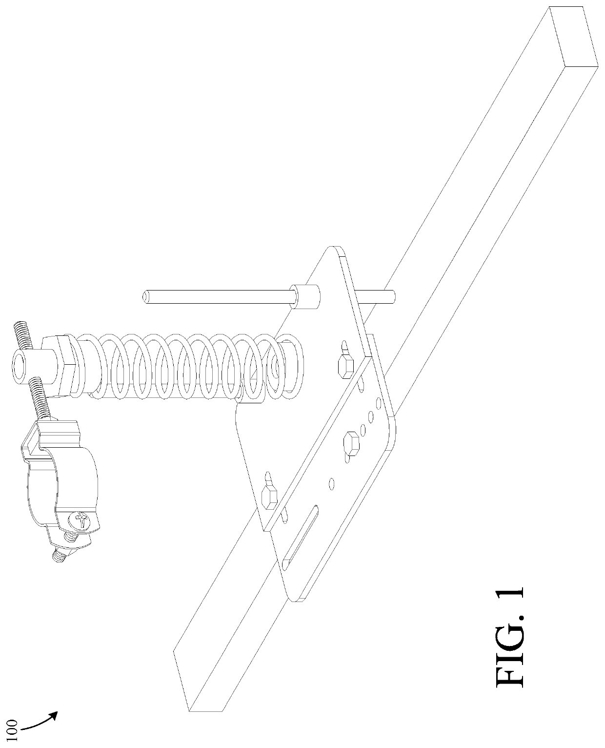
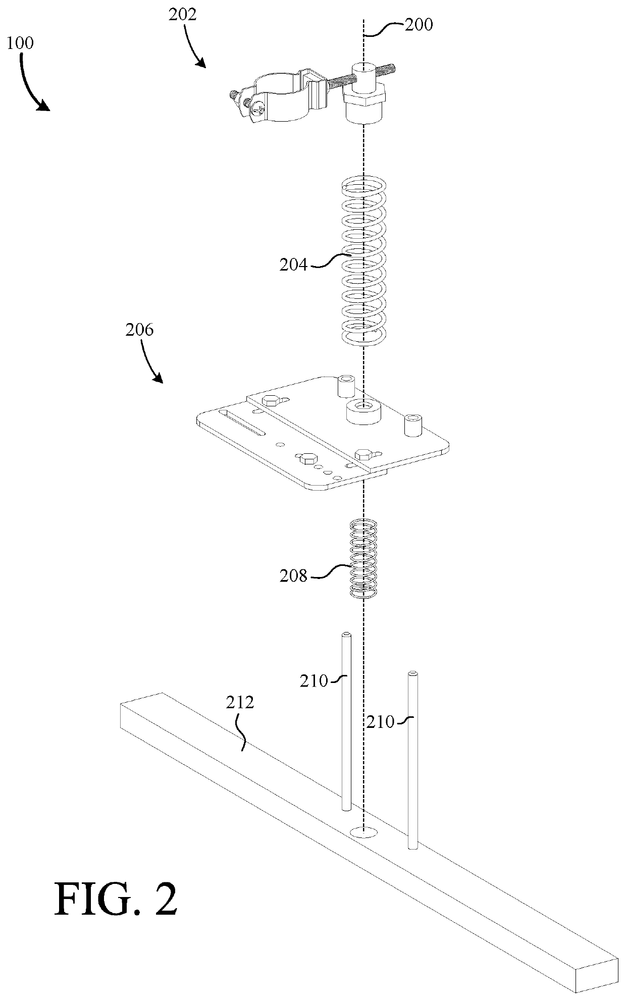
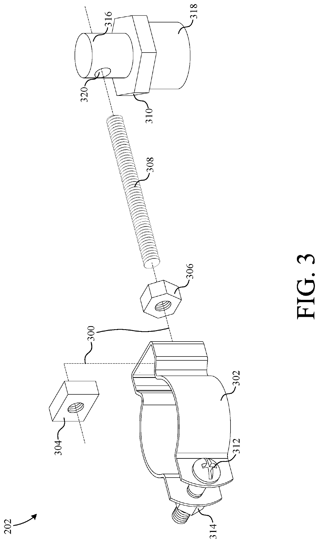
[0045]FIG. 1 shows a perspective view of a drill jig 100 according to one embodiment of the present invention. Drill jig 100 is adapted to be used in conjunction with a drill press (not shown in FIG. 1). More specifically, jig 100 mou...


PUM

PropertyMeasurementUnit
forceaaaaaaaaaa
stiffnessaaaaaaaaaa
tensionaaaaaaaaaa

Abstract

A novel drill jig includes an edge alignment guide, a hole-spacing assembly, a second guide, a biasing member, and an actuator. The edge alignment guide is configured to abut an edge of a workpiece to facilitate movement of the workpiece along a first straight line. The hole-spacing assembly includes a protrusion disposed to engage a preexisting hole in a workpiece positioned by the edge alignment guide. The second guide is coupled to the hole-spacing assembly and is configured to facilitate movement of the hole-spacing assembly along a second straight line perpendicular to the first straight line. The first biasing member is coupled to the hole-spacing assembly and is operative to exert a force on the hole-spacing assembly in a direction parallel to the second straight line. An actuator moves the hole-spacing assembly along the second straight line via the first biasing member.

Description

CROSS REFERENCE TO RELATED APPLICATIONS[0001]This application is a continuation-in-part of U.S. patent application Ser. No. 16 / 167,367, filed on Oct. 22, 2018 by the same inventor, which is incorporated by reference herein in its entirety.BACKGROUND OF THE INVENTIONField of the Invention[0002]This invention relates generally to drill jigs, and more particularly to a jig facilitating the linear alignment and relative spacing between drill holes.Description of the Background Art[0003]In construction and manufacturing industry, it is often desirable to drill multiple holes in a workpiece. Oftentimes, the workpiece specifications require holes to be drilled a particular distance from a previously drilled hole. One way this is accomplished is by using a drill stencil, which is essentially a rigid plate having a plurality of holes with fixed spacing therebetween. Before the drilling process, a user positions the stencil on the workpiece by some suitable means (e.g., tape, adhesive, clamp,...

Claims


Application Information

Patent Timeline
Patent Type & Authority Patents(United States)
IPC IPC(8): B23B47/28B25H1/00B23Q9/00
CPCB23B47/28B23Q9/0028B25H1/0078B23B2260/136B23B2270/34B25H1/0064B23B47/287B23B2247/04
Inventor DEGOWSKE, ROBERT JAMES
Owner DEGOWSKE ROBERT JAMES
Learn More