
Screw-in hanging line pile and its installation device suitable for hard soil construction

A technology for installing devices and wire piles, which is applied to sheet pile walls, infrastructure projects, roads, etc., can solve problems such as economic losses, unqualified construction quality, and inability to carry out construction, and achieve the effect of ensuring normal progress.

Active Publication Date: 2021-07-23
CHONGQING JIAOTONG UNIVERSITY
View PDF6 Cites 0 Cited by
  • Summary
  • Abstract
  • Description
  • Claims
  • Application Information

AI Technical Summary

Problems solved by technology

[0002] With the vigorous development of the construction industry, the country's requirements for the quality of construction are becoming more and more stringent, and the smoothness of the road surface is one of the measures of the quality of municipal road construction, and its importance cannot be ignored. The most commonly used construction method in China, but the traditional wire-hanging paving is firstly driven by manual piles, and then manually adjusted with a scale according to the measured paving elevation data of each pile, and then the wire is hung. This method has great advantages Disadvantages, first, time-consuming and laborious, low efficiency, low accuracy, huge labor cost investment, and often affected by human factors, the construction quality is unqualified, resulting in unnecessary economic losses. Second, for special geological construction (such as Frozen soil or hard soil), due to the hard soil, it is difficult to manually drive the hanging pile into the road bed, resulting in the inability to carry out the construction

Method used


Image

  • Screw-in hanging line pile and its installation device suitable for hard soil construction
  • Screw-in hanging line pile and its installation device suitable for hard soil construction
  • Screw-in hanging line pile and its installation device suitable for hard soil construction

Examples


Embodiment Construction

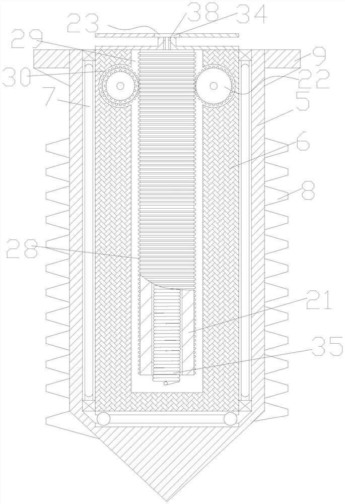
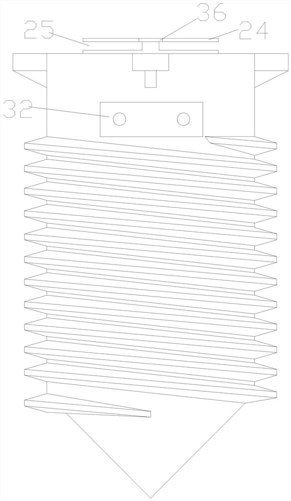
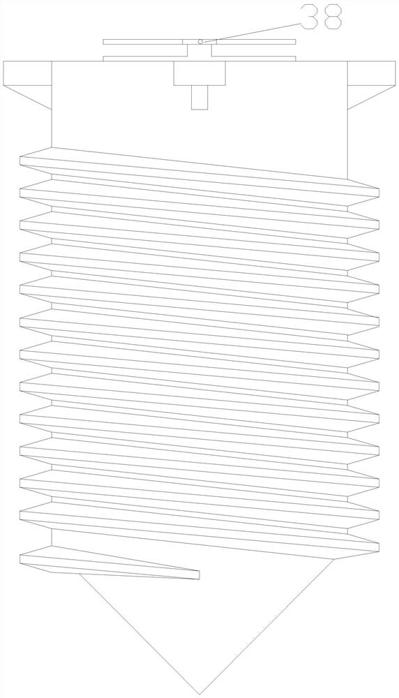
[0024] figure 1 It is a cross-sectional view of the screw-in type hanging wire pile of the present invention, figure 2 It is the front view of the screw-in type hanging stake of the present invention, image 3 It is the rear view of the screw-in type hanging stake of the present invention, Figure 4 It is a top sectional view of the screw-in type hanging wire pile of the present invention, Figure 5 It is a structural schematic diagram of the mounting device of the present invention, Image 6 It is a partial enlarged view of A place of the installation device of the present invention, Figure 7 It is a top view of the mounting device of the present invention, Figure 8 It is a sectional view of C-C of the mounting device of the present invention, Figure 9It is a schematic diagram of the connection between the present invention and a wire and a microcomputer, as shown in the figure: a screw-in type hanging pile and its installation device suitable for hard soil construct...


PUM


Abstract

The invention discloses a screw-in type hanging pile suitable for hard soil construction and its installation device. The screw-in hanging pile includes a cylindrical shell, a cylindrical coaxial positioning seat arranged in the shell, and a cylindrical coaxial positioning seat set in the shell. Between the rolling bearing and the positioning seat, the outer wall of the casing is provided with a screw for breaking the ground and a driving boss for cooperating with the installation device. The inner ring of the rolling bearing is fixed and sleeved on the positioning seat along the axial direction. The installation device includes a triangular operating platform , screw, planetary gear, sun gear sleeve, triangular planet carrier, driving motor I, and screw rod are vertically fixed on the bottom of the triangular operating platform, and the middle and three corners of the triangular planet carrier are respectively provided with bearings I and II. The inner ring of the bearing II is overlaid on the screw, and the inside of the inner ring is provided with threads that match the screw. The inner ring of the bearing II extends downward to form a drive ring. The output shaft of the drive motor I fits through the bearing I and is coaxially fixed on the Top of sun gear sleeve.

Description

technical field [0001] The invention relates to the field of municipal construction, in particular to a screw-in type hanging pile suitable for hard soil construction and an installation device thereof. Background technique [0002] With the vigorous development of the construction industry, the country's requirements for the quality of construction are becoming more and more stringent, and the smoothness of the road surface is one of the measures of the quality of municipal road construction, and its importance cannot be ignored. The most commonly used construction method in China, but the traditional wire-hanging paving is firstly driven by manual piles, and then manually adjusted with a scale according to the measured paving elevation data of each pile, and then the wire is hung. This method has great advantages Disadvantages, first, time-consuming and laborious, low efficiency, low accuracy, huge labor cost investment, and often affected by human factors, the constructio...

Claims


Application Information

Patent Timeline
Patent Type & Authority Patents(China)
IPC IPC(8): E01C23/01E02D5/80
CPCE01C23/01E02D5/80
Inventor 王羽徐航付有为杨军
Owner CHONGQING JIAOTONG UNIVERSITY
Learn More