

Progressive cavity helical device
a cavity and helical technology, applied in the direction of machines/engines, liquid fuel engines, borehole/well accessories, etc., can solve the problems of rotor wear, problems such as problems, and loss of use during downtim
Inactive Publication Date: 2001-06-28
BICO DRILLING TOOLS
View PDF0 Cites 48 Cited by
- Summary
- Abstract
- Description
- Claims
- Application Information
AI Technical Summary
Problems solved by technology
Because of the required sealing and sliding contact concept of a Moineau pump, the stator and the rotor become subject to extensive wear, which necessitates frequent replacement of the stator and / or the rotor.
Commercially available Moineau pumps, as well as those disclosed in the prior art, require extensive disassembly of the pumping apparatus to replace the worn stator and / or rotor, in addition to the down time loss of use.
In a progressive cavity pump or motor, problems arise because the axial centerline of the rotor is required to orbit or gyrate relative to the centerline of the stator.
Thus, there is a great deal of flexture that must be accounted for to obtain long life of parts.
Some efficiency of the pump / motor is lost because the elastomer mold must be thicker at the peaks of the helicoid in order to create the progressive cavity.
This lack of uniform thickness creates compressibility differences which, at increasing pressures, causes bypass of the fluids being pumped.
Thus, the pump / motor reaches a point where it is less efficient at ever increasing pressure.
Rubber used as the stator contact surface is not preferable in high temperature environments because of its low heat conductivity.
In addition, as progressive cavity devices increase in diameter and / or length, flow characteristics to maintain a successful and long lasting bond of the rubber to a steel housing becomes more difficult.
Also, where hydrocarbons make up the material to be pumped, such as in oil producing wells, rubber is known to deteriorate.
Method used
View moreImage
Smart ImageViewing Examples

Examples
embodiment b
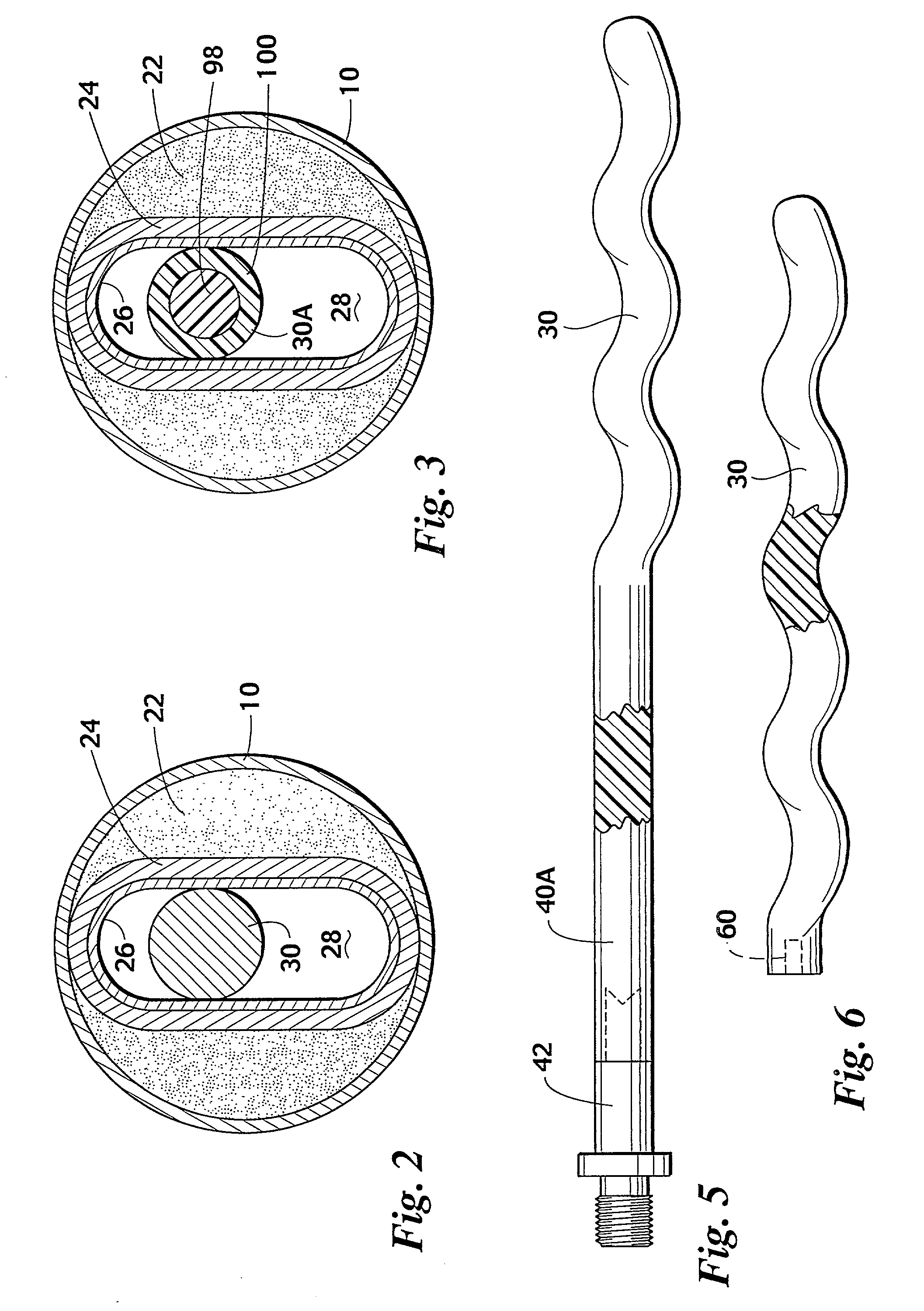
[0035] In this embodiment, areas 22 and 24 are made of a composite material, while the helicoid liner 26 is a thermoplastic resin.
embodiment c
[0036] In this embodiment, composite material will make up the total stator, including areas 22, 24 and 26.
embodiment d
[0037] In this embodiment, areas 22 and 24 are of hardened materials, either machinable or moldable, such as steel or ceramics, with the bonded inner lining 26 being formulated of a composite material.
Login to View More PUM
| Property | Measurement | Unit |
|---|---|---|
| Elastomeric | aaaaa | aaaaa |
| Resilience | aaaaa | aaaaa |
Abstract
Description
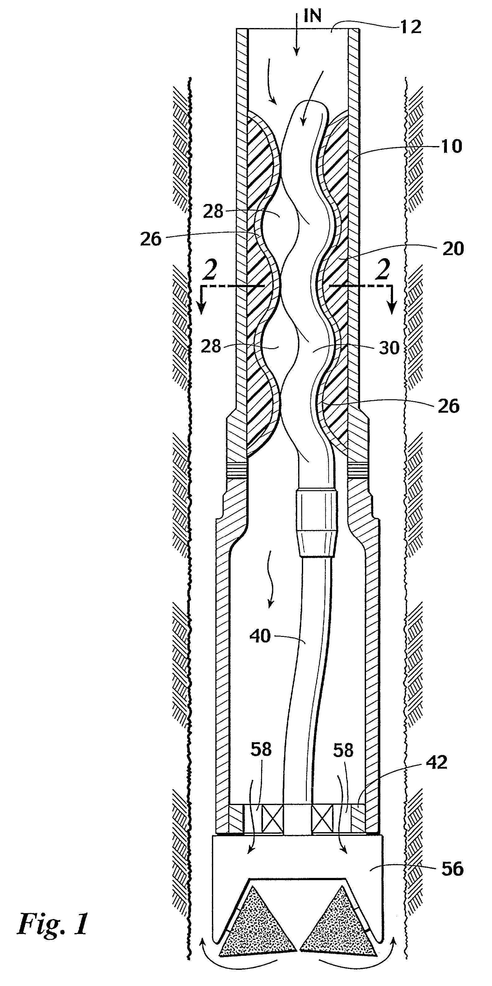
[0001] 1. Field of the Invention[0002] This invention relates to improvements in progressive cavity style devices of the type composed of a helicoidal rotor acting with a complimentary helicoidal stator and also well known as a "Moineau pump" which may be used as a pump or as a motor to drive other equipment.[0003] 2. Prior Art[0004] Progressive cavity helical devices have been known since their invention was disclosed in U.S. Pat. No. 1,892,217, entitled "Gear Mechanism" to Moineau. The helicoidal rotor and the stator engage with each other along a sealing line to create cavities which progress axially as the rotor is rotated relative to the stator. Because of the required sealing and sliding contact concept of a Moineau pump, the stator and the rotor become subject to extensive wear, which necessitates frequent replacement of the stator and / or the rotor. Commercially available Moineau pumps, as well as those disclosed in the prior art, require extensive disassembly of the pumping ...
Claims
Login to View More Application Information
Patent Timeline
 IPC IPC(8): B29C53/58B29C53/60F03C2/08F04C2/08F04C2/107
CPCB29C53/58B29C53/60B29L2031/7498B29L2031/75E21B43/129F03C2/08F04C2/084F04C2/1071F04C2/1073F04C13/008F05C2253/04
InventorWOOD, STEVEN M.
OwnerBICO DRILLING TOOLS