Control apparatus for variably operated engine valve mechanism of internal combustion engine
a control apparatus and valve mechanism technology, which is applied in the direction of valve arrangement, yielding coupling, coupling, etc., can solve the problems of reducing energy efficiency, energy and generating loss in the oil pump
- Summary
- Abstract
- Description
- Claims
- Application Information
AI Technical Summary
Benefits of technology
Problems solved by technology
Method used
Image

Examples
first embodiment
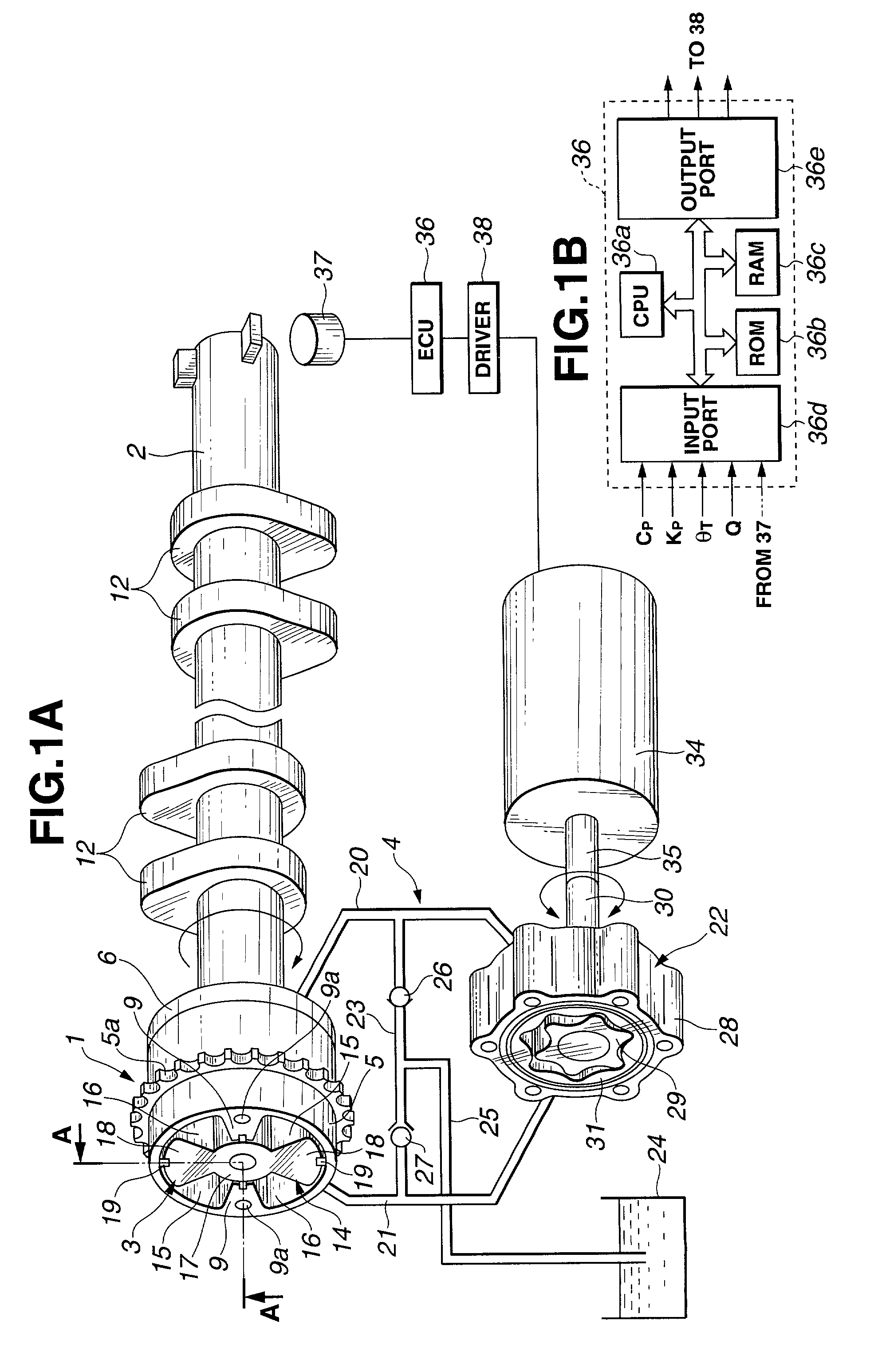
[0029] FIG. 1A shows a first preferred embodiment of a control apparatus for a variably operated engine valve mechanism, a phase converter of which is applicable to a vane type phase converter.
[0030] That is to say, the control apparatus includes: a sprocket 1 which is a rotary body revolved with a crankshaft (not shown) of an internal combustion engine via a timing chain; a camshaft 2 relatively pivotable with respect to the sprocket 1; a phase converter 3 disposed between the sprocket 1 and the camshaft 2 to convert a relatively pivotal position of both of the sprocket 1 and the camshaft 2; and a hydraulic circuit 4 to operate the phase converter 3.
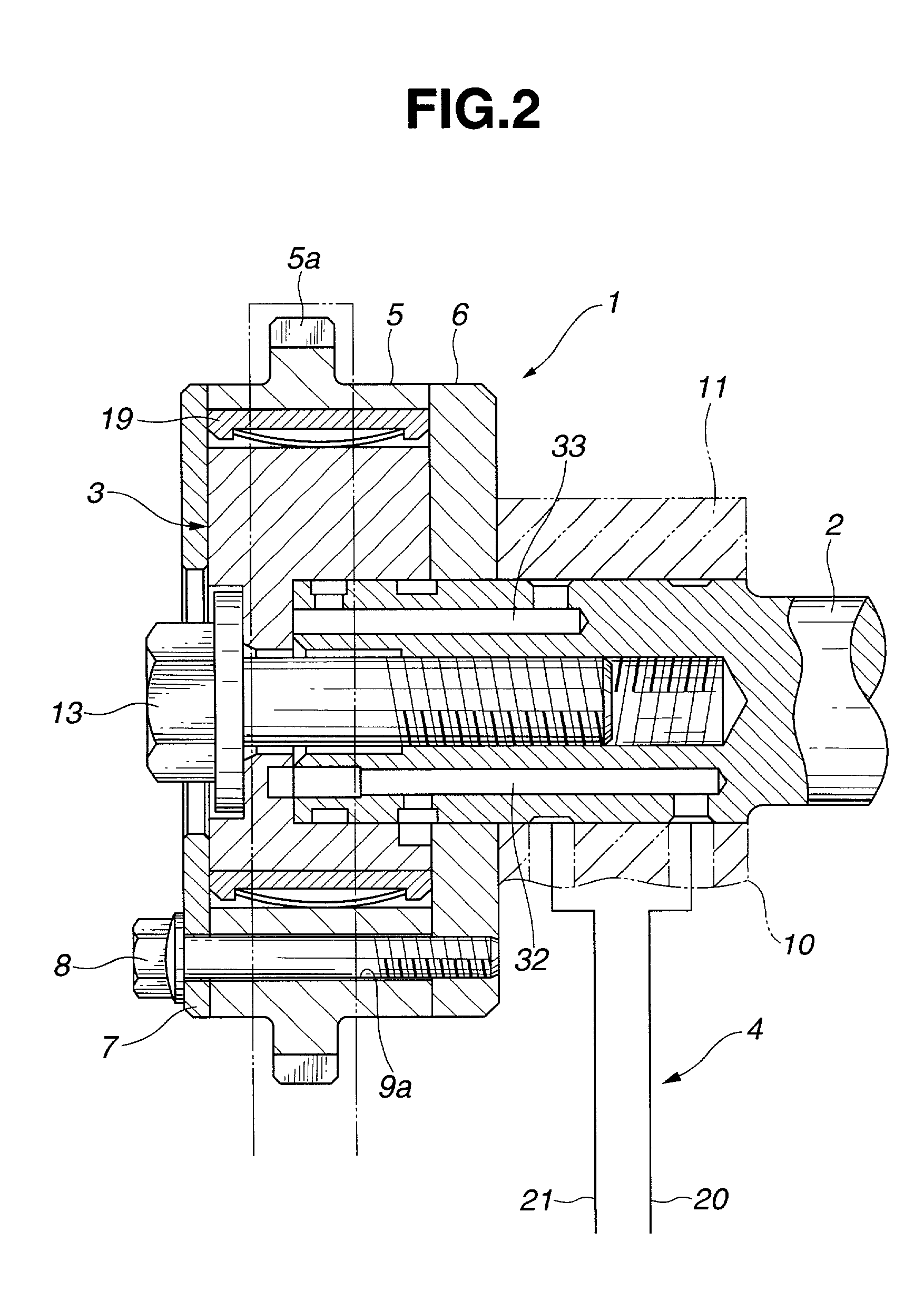
[0031] FIG. 2 shows a structure of the sprocket 1.
[0032] As shown in FIG. 2, the sprocket 1 includes: a housing 5 having a tooth 5a with which the timing chain is meshed; a rear corner 6 which encloses an opening of a rear end of a housing 55; and a front cover 7 of a substantially disc shape of a lid enclosing the opening of a front en...
second embodiment
[0070] FIG. 4 shows a second preferred embodiment of the control apparatus for the variably operated engine valve according to the present invention.
[0071] In the second embodiment, the phase converter 3 is applicable to the variable open-and-closure timing controlling apparatus disclosed in a Japanese Patent Application First Publication No. Heisei 6-2516 which corresponds to a U.S. Pat. No. 5,557,983 issued on Sep. 24, 1996, the disclosure of which is herein incorporated by reference.
[0072] In the second embodiment, the converter of the vane type is utilized as a hydraulic actuator of an operation mechanism to operate the phase converter 3.
[0073] The phase converter 3 is constituted as shown in FIGS. 5 and 6.
[0074] In FIGS. 5 and 6, reference numeral 40 is a drive axle of an inner side hollow shape, reference numeral 41 is a camshaft disposed on the same axle as an outer periphery of the drive axle 40 for each cylinder, reference numeral 42 denotes a control mechanism for varying ...
third embodiment
[0086] FIG. 7 shows a third preferred embodiment of the control apparatus for the variably operated engine valve mechanism according to the present invention.
[0087] The phase converter 3 and oil pump 22 are the same as those in the second embodiment. In the third embodiment, the hydraulic actuator 70 of the operation mechanism 58 is of a hydraulic cylinder type.
[0088] In details, the hydraulic actuator 70 includes: a cylinder housing 71 disposed on the other end of the control shaft 59 and extended along a direction to an axle (viz., piston rod) of a piston 74A, the piston 74 being slidably housed partitioning an inner space of the cylinder 71 into first hydraulic oil chamber 72 and second hydraulic oil chamber 73 and the piston rod 74A having an outer periphery and linked to a center of the piston 74.
[0089] The piston rod 74A have one free end 74b through which each end of the cylinder housing 71 is penetrated and is linked to a tongue-shaped control plate 75 fixed on a tip of the ...
PUM
 Abstract
Description
Claims
Application Information
 - R&D Engineer
- R&D Manager
- IP Professional
- Industry Leading Data Capabilities
- Powerful AI technology
- Patent DNA Extraction
Browse by: Latest US Patents, China's latest patents, Technical Efficacy Thesaurus, Application Domain, Technology Topic.
© 2024 PatSnap. All rights reserved.Legal|Privacy policy|Modern Slavery Act Transparency Statement|Sitemap