
Projection apparatus and three-dimensional image display apparatus

Inactive Publication Date: 2001-09-13
MINOLTA CO LTD
View PDF0 Cites 11 Cited by
  • Summary
  • Abstract
  • Description
  • Claims
  • Application Information

AI Technical Summary

Benefits of technology

[0020] The three-dimensional image display apparatus according to the present invention can properly project the image onto the surface of the screen to achieve optimum display of a three-dimensional image since light from the display device is not vignetted.
[0021] It is therefore an object of the present invention to provide a projection apparatus and a three-dimensional image display apparatus which can facilitate the insertion of an additional processing optical system therein without vignetting of light from a display device.

Problems solved by technology

It has been very difficult for optical design to-prevent such vignetting.
The former, however, results in threefold increase in display time since one color cross-section image is generated by projecting three cross-section images for R, G and B. The latter which requires the three DMDs is unfavorable because of increased costs.
This results in the presence of a blurred image among the cross-section images corresponding to the color components projected on the screen 38, decreasing the quality of the displayed image.
This is because, if the focal length f1 takes an excessively small positive or negative value, it is difficult to provide the both side telecentricity and, accordingly, a required level of performance (point spread, with an object point fixed) is not obtained.
However, the provision of too many lenses results in the increased size of the entire apparatus.

Method used


Image

  • Projection apparatus and three-dimensional image display apparatus
  • Projection apparatus and three-dimensional image display apparatus
  • Projection apparatus and three-dimensional image display apparatus

Examples


example 2

[0139] [Example 2]

[0140] FIG. 10 shows the optical path of the both side telecentric optical system 511a2 according to Example 2. In the both side telecentric optical system 511a2, the front-group lens system (first-group lens system) G1 comprises, in order from the display device side: a lens L201 having surfaces r201 and r202; a lens L202 having surfaces r203 and r204 a lens L203 having surfaces r205 and r206; a lens L204 having surfaces r206 and r207; a lens L205 having surfaces r207 and r208; and a lens L206 having surfaces r209 and r210.

[0141] The rear-group lens system (second-group lens system) G2 is provided in symmetric relation to the front-group lens system G1 with respect to the diaphragm S having a surface r211. The rear-group lens system G2 comprises, in order from the display device side: a lens L207 having surfaces r212 and r213; a lens L208 having surfaces r214 and r215; a lens L209 having surfaces r215 and r216; a lens L210 having surfaces r216 and r217; a lens L21...

example 3

[0159] [Example 3]

[0160] FIG. 12 shows the optical path of the both side telecentric optical system 511a3 according to Example 3. In the both side telecentric optical system 511a3, the front-group lens system (first-group lens system) G1 comprises, in order from the display device side: a lens L301 having surfaces r301 and r302; a lens L302 having surfaces r303 and r304; a lens L303 having surfaces r305 and r306; a lens L304 having surfaces r306 and r307; and a lens L305 having surfaces r308 and r309.

[0161] The rear-group lens system (second-group lens system) G2 is provided in symmetric relation to the front-group lens system G1 with respect to the diaphragm S having a surface r310. The rear-group lens system G2 comprises, in order from the display device side: a lens L306 having surfaces r311 and r312; a lens L307 having surfaces r313 and r314; a lens L308 having surfaces r314 and r315; a lens L309 having surfaces r316 and r317; and a lens L310 having surfaces r318 and r319. The s...

example 4

[0167] [Example 4]

[0168] FIG. 14 shows the optical path of the both side telecentric optical system 511a4 according to Example 4. The both side telecentric optical system 511a4 is similar in lens arrangement to the both side telecentric optical system 511a3 of Example 3. More specifically, in the both side telecentric optical system 511a4, the front-group lens system (first-group lens system) GI comprises, in order from the display device side: a lens L401 having surfaces r401 and r402; a lens L402 having surfaces r403 and r404; a lens L403 having surfaces r405 and r406; a lens L404 having surfaces r406 and r407; and a lens L405 having surfaces r408 and r409.

[0169] The rear-group lens system (second-group lens system) G2 is provided in symmetric relation to the front-group lens system G1 with respect to the diaphragm S having a surface r410. The rear-group lens system G2 comprises, in order from the display device side: a lens L406 having surfaces r411 and 412; a lens L407 having su...


PUM


Abstract

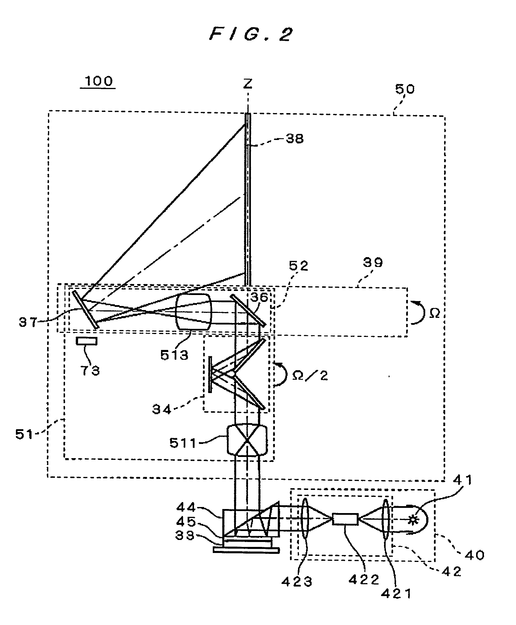
A projection apparatus and a three-dimensional image display apparatus are provided. Light being separated into R, G and B color components reflected from a digital micromirror device through a TIR prism is directed into a both side telecentric optical system, is image-formed in the both side telecentric optical system, and is then directed into a processing optical system including optical path length compensators, dichroic mirrors, mirrors and an image rotation compensating mechanism without being vignetted The both side telecentric optical system is designed to satisfy |f1|>75 mm where f1 is the focal length of the entire both side telecentric optical system. The both side telecentric optical system has a long back focal length to allow the processing optical system to be easily placed in front of a projection optical system. Thus, the projection apparatus and the three-dimensional image display apparatus facilitate the insertion of the processing optical system therein.

Description

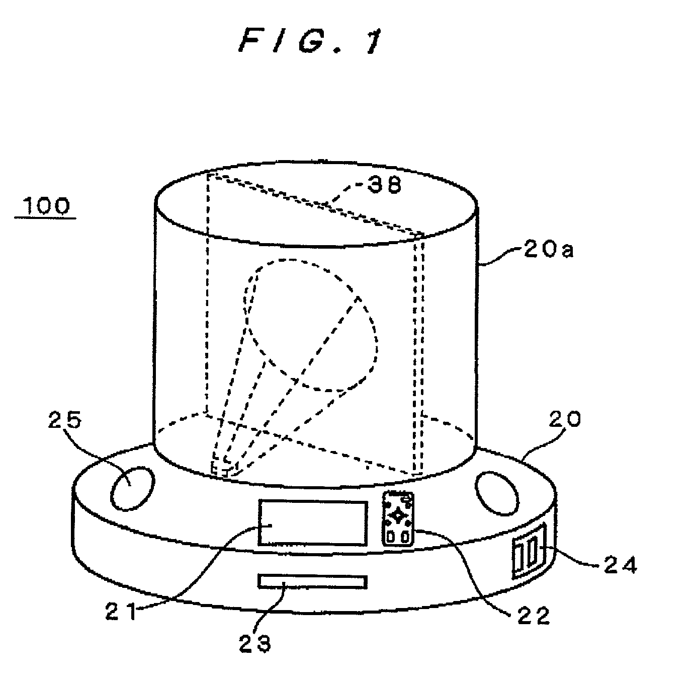
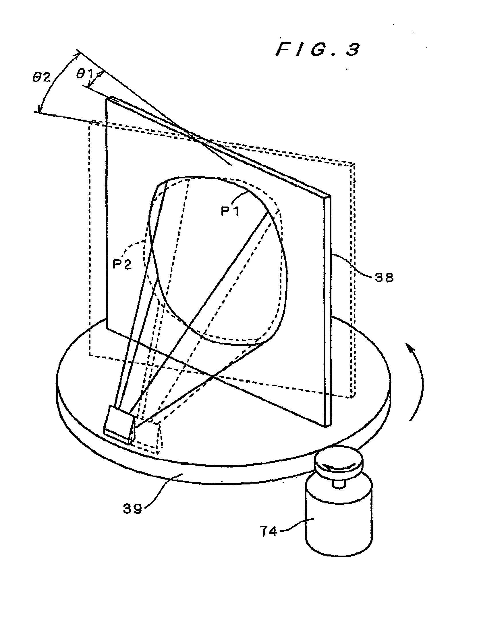
[0001] This application is based on application No. 2000-17162 filed in Japan, the contents of which ate hereby incorporated by reference.[0002] 1. Field of the Invention[0003] The present invention relates to a projection apparatus for displaying images by projection, and a three-dimensional (3-D) image display apparatus.[0004] 2. Description of the Background Art[0005] Projection apparatuses such as projectors which display desired images by projection on a screen and the like are conventionally known. For example, a reflective projection apparatus comprises a light source, a reflective display device, and a projection optical system. While an image is displayed on the display device based on digital image data, light from the light source is directed onto the display device, and the light reflected from the display device is projected onto a projection target such as a screen by the projection optical system to display an image on the projection target.[0006] The projection appar...

Claims


Application Information

Patent Timeline
IPC IPC(8): G03B35/16G02B13/22G02B13/24G02B27/22G02B27/64G03B21/00H04N13/00
CPCG02B13/22G02B27/2285G02B27/642G03B21/00H04N13/0422H04N13/0427H04N13/0459H04N13/0493G03B21/005G02B30/54H04N13/324H04N13/363H04N13/365H04N13/393
Inventor KUISEKO, MANAMIYOSHII, KENMIYAZAKI, MAKOTO
Owner MINOLTA CO LTD
Learn More