Method of laying data cables and the like in underground pipes and pipe-cable combinations

a technology of underground pipes and data cables, which is applied in the direction of shaft linings, tunnel linings, pipe protection against damage/wear, etc., can solve the problems of clogging sewage pipes, linings are likely to be damaged, and use of liners can prolong the useful life of internal pressure or open underground pipes for many years

Inactive Publication Date: 2001-11-22
PRUSAK MARTIN
View PDF0 Cites 19 Cited by
  • Summary
  • Abstract
  • Description
  • Claims
  • Application Information

AI Technical Summary

Benefits of technology

0012] An object of the present invention is to provide a novel and improved method of ensuring that the cable or cables which is or which are confined in a sewage pipe or the like is or are invariably protected against mechanical or chemical damage during and subsequent to laying.

Problems solved by technology

Unless a complete renovation of underground piping is unavoidable due to the condition of existing pipes, the utilization of liners can prolong the useful lives of internally pressurized or open underground pipes for many years, e.g., for many decades.
A drawback of such proposal is that the thus installed protective tubing is likely to be damaged during periodic cleaning of the sewage pipes.
Moreover, debris and other impurities are likely to be intercepted by the suspended tubes and / or by their clamps which can result in rapid clogging of the sewage pipes.

Method used


Image

  • Method of laying data cables and the like in underground pipes and pipe-cable combinations
  • Method of laying data cables and the like in underground pipes and pipe-cable combinations
  • Method of laying data cables and the like in underground pipes and pipe-cable combinations

Examples


Embodiment Construction

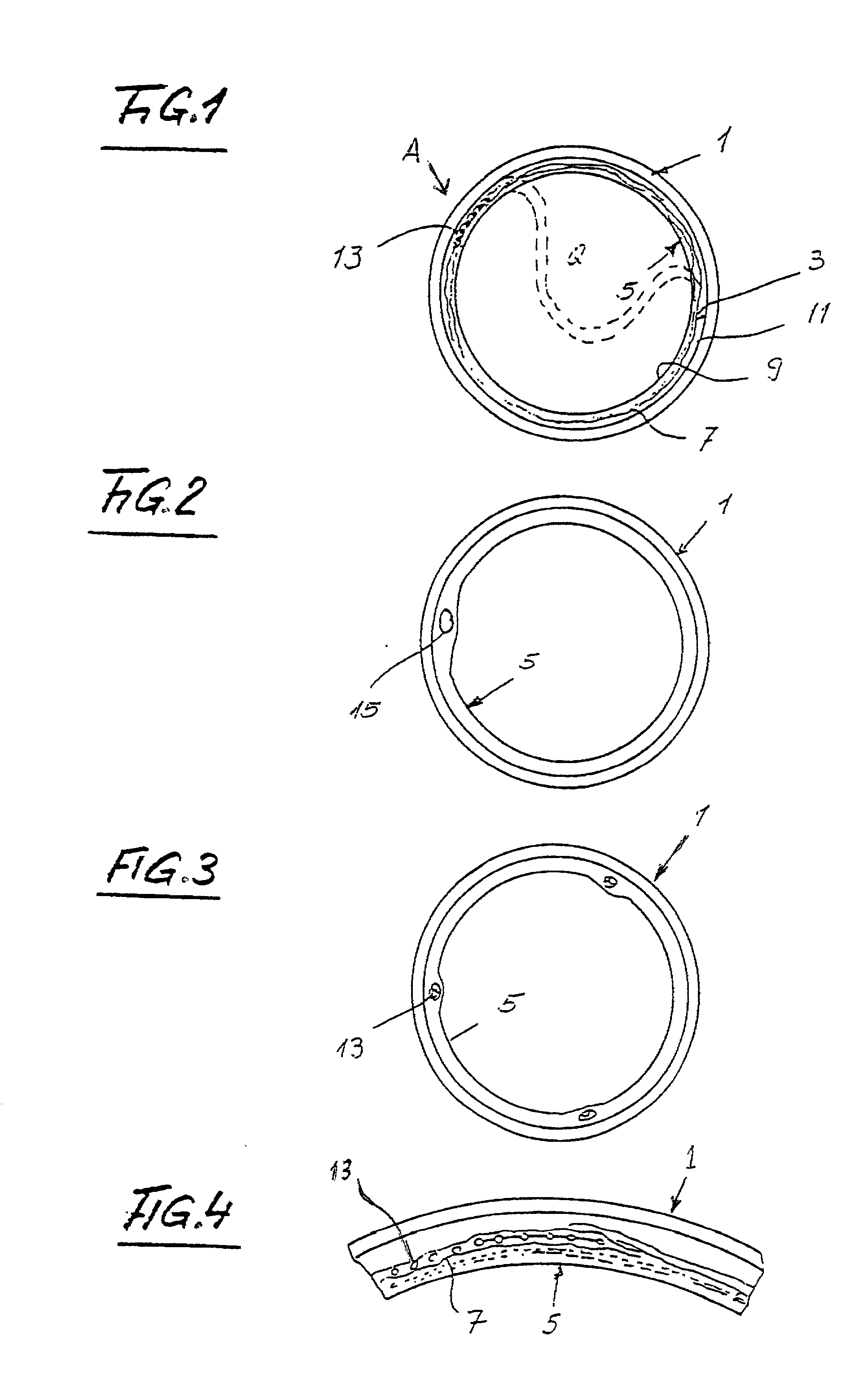
[0046] FIG. 1 shows a pipe 1 which consists of or contains concrete, steel, a synthetic plastic material, earthenware, glass or the like. Such pipe can be utilized to confine and convey water (such as rain water), liquid or partly liquid sewage or the like. The illustrated pipe 1 has a circular cross-sectional outline; however, it is equally possible to practice the method of the present invention by employing pipes having oval, square, rectangular or other polygonal cross-sectional outlines.

[0047] Initially (i.e., when new), the pipe 1 has a smooth internal surface 3. However, due to frictional engagement with conveyed floating sewage, corrosion, other types of wear, shaking, bending (such as that due to sinking of the ground beneath portions of or the entire pipe), etc., the pipe 1 can undergo more or less serious damage including the development of cracks, breaks, leaks and / or shifts at the junctions between the end portions of neighboring pipes and / or as a result of floating awa...


PUM

PropertyMeasurementUnit
anglesaaaaaaaaaa
electric currentaaaaaaaaaa
metallicaaaaaaaaaa

Abstract

One or more electric and/or data transmitting cables are confined in an elongated strip-shaped body containing a hardenable resin or the like, and the body is placed against a portion of the internal surface of an underground sewage, water or other pipe. An expandible tubular liner is thereupon introduced into the pipe and is expanded to press the body against the pipe. The body is caused to set, by conveying a hot fluid through the liner and/or by electrically heating the cable or cables, and to adhere to the internal surface of the pipe. The liner can remain in the pipe and can be bonded to the strip-shaped body and/or to the remaining portion of the internal surface of the pipe. Alternatively, the liner is caused to collapse and is withdrawn from the pipe once the strip-shaped body is bonded to the internal surface of the pipe.

Description

[0001] The present invention relates to improvements in methods of laying and in combinations of parts for confining data cables, electrical conductors and the like in existing underground pathways including those defined by sewage pipes, water pipes, gas pipes and others.[0002] In many communities, including large cities as well as smaller inhabited developments, the pipes (this term is utilized generically and embraces all or practically all types of underground as well as many aboveground passageways and conduits) are already utilized as a means for accommodating, confining, shielding and supporting information-, current-and / or signal-transmitting cables in the form of glass fibers, metallic wire-like conductors and others. An advantage of such mode of confining and shielding cables (this term will be employed hereinafter to cover all kinds of wire-like, filamentary and other components which must be laid to and / or from houses, apartment buildings, office buildings, factories, sh...

Claims


Application Information

Patent Timeline
Patent Type & Authority Applications(United States)
IPC IPC(8): E02F5/10E02B9/06E03F3/00E03F3/06F16L1/00F16L1/038F16L7/00F16L55/165G02B6/44G02B6/46G02B6/50H02G1/06H02G1/08H02G3/12H02G9/00H02G9/06
CPCE03F3/00E03F5/022F16L7/00F16L55/1656G02B6/4459G02B6/502G02B6/508H02G1/08H02G9/06
Inventor PRUSAK, MARTIN
Owner PRUSAK MARTIN
Why Eureka
Try Eureka