
Liquid dispenser

a dispenser and liquid technology, applied in the direction of liquid transfer devices, volume meters, instruments, etc., can solve the problems of dispensers being susceptible to being knocked over, stolen or lost, containers tend to be smaller and/or limited capacity, and dispensers are not without drawbacks

Inactive Publication Date: 2002-01-17
HENKEL IP & HOLDING GMBH
View PDF0 Cites 38 Cited by
  • Summary
  • Abstract
  • Description
  • Claims
  • Application Information

AI Technical Summary

Problems solved by technology

Unfortunately, however, these dispensers are susceptible to being knocked over, stolen, or lost because, in general, they merely sit on countertops and in wash basin areas.
Further, the containers tend to be of smaller and / or limited capacity.
These types of dispensers are not without their drawbacks either.
For example, they can be messy.
That is, many dispensers have pump mechanisms which are awkward for the user.
However, this can cause soap to drip on the lever and other structures of the soap dispenser.
Likewise, other push button type dispensers consist of elongated pumping members which also may become covered with liquid soap and may be prone to breaking.
Still further, with many of these soap dispensers, sanitation can be a problem.
Because they are integrated with the dispenser itself, it is often not easy to replace the pumping mechanism.
Thus, the potential for wasting soap is high.
Further, it is not uncommon to place soap bottle refills within soap dispenser housings which are not intended to fit within the housing being used.
This leads to an insecure fit within the housing, potentially causing problems with dispensing, closing the housing, and wobble of the bottle within the housing.

Method used


Image

  • Liquid dispenser
  • Liquid dispenser
  • Liquid dispenser

Examples


Embodiment Construction

[0018] The following descriptions are of exemplary embodiments of the invention only, and are not intended to limit the scope, applicability or configuration of the invention in any way. Rather, the following description is intended to provide a convenient illustration for implementing various embodiments of the invention. As will become apparent, various changes may be made in the function and arrangement of the elements described herein without departing from the spirit and scope of the invention. For example, though not specifically described, many shapes and orientations of the housing and refill bottle and alternative dispensing and pumping mechanisms should be understood to fall within the scope of the present invention.

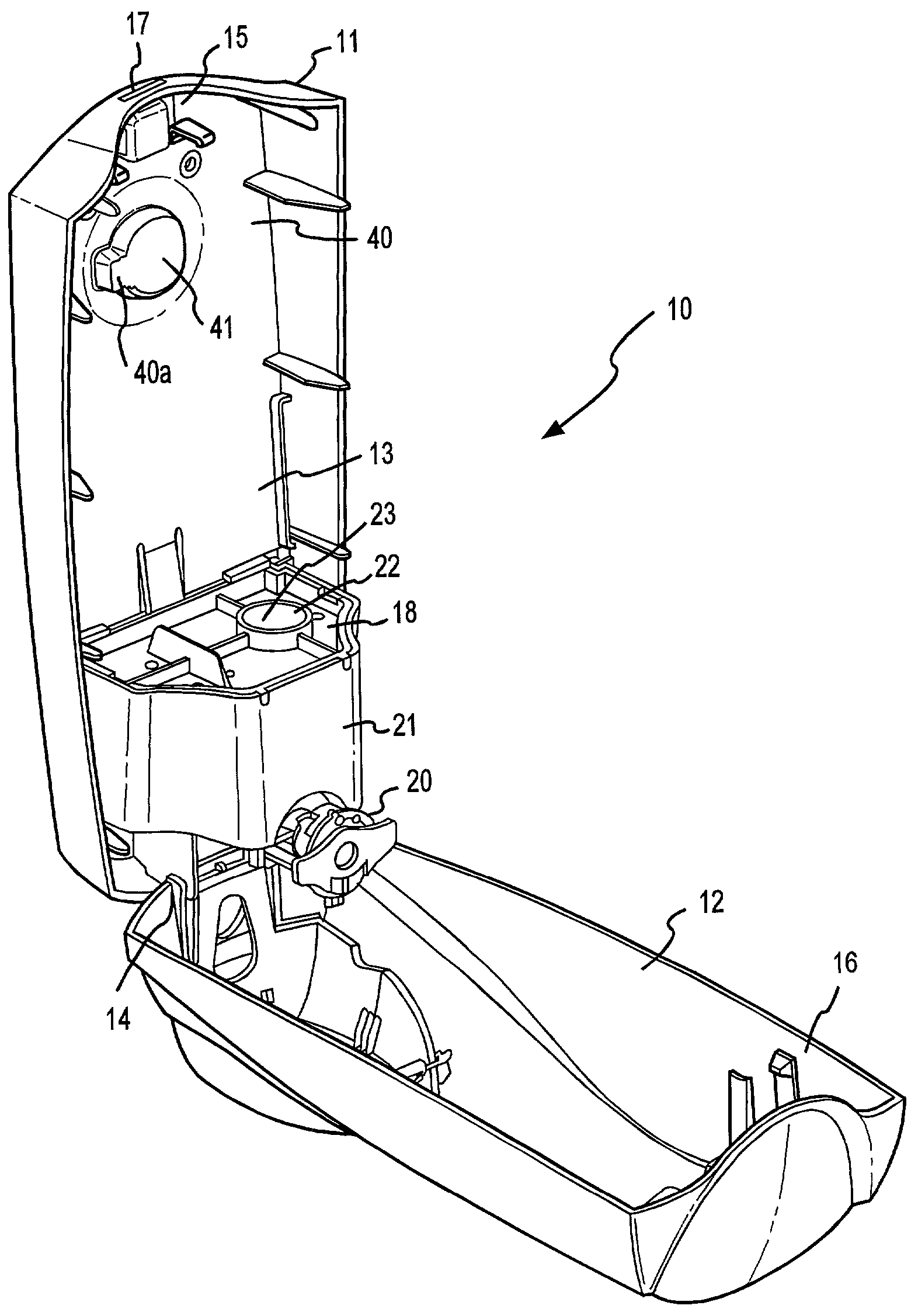
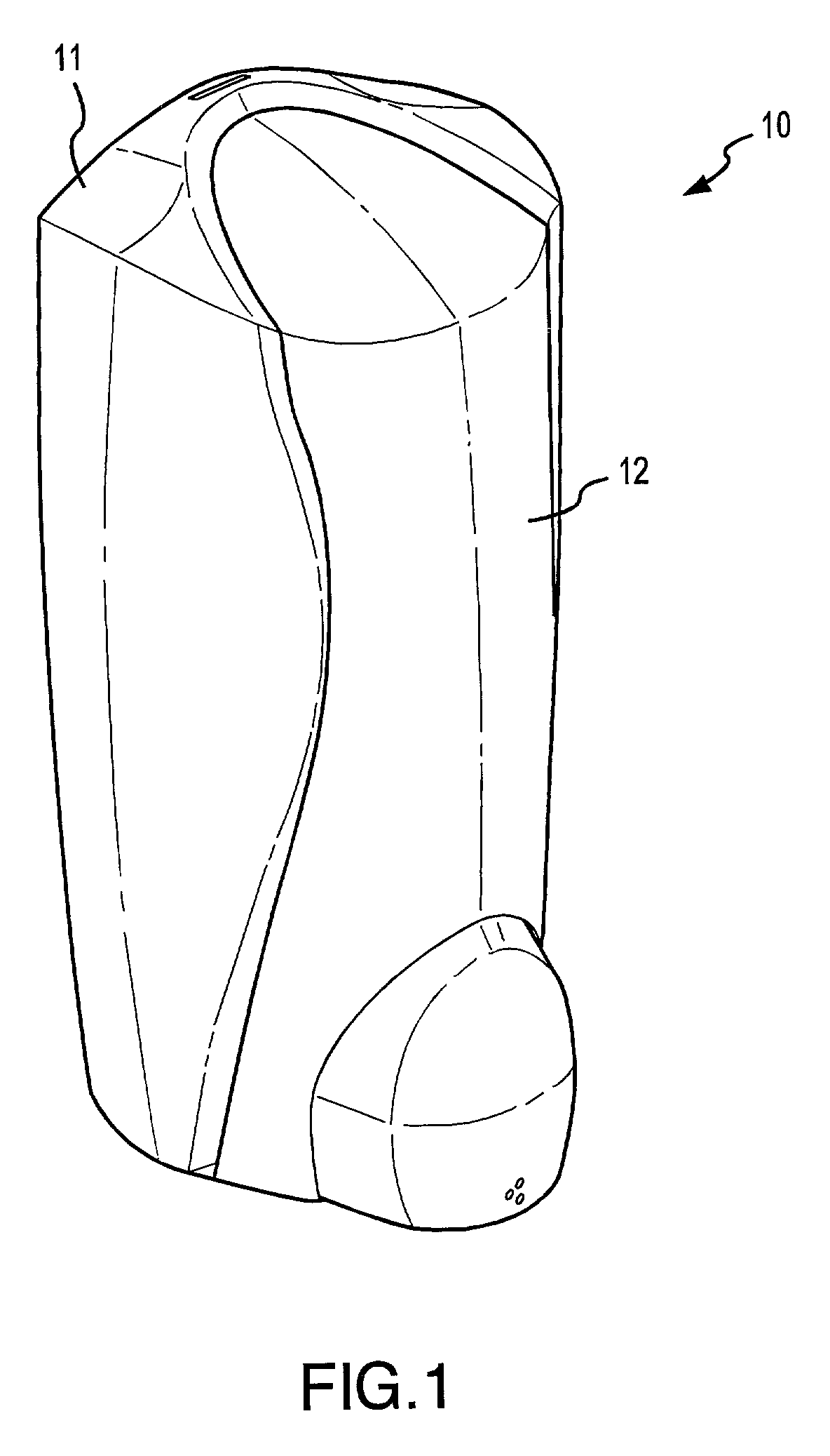
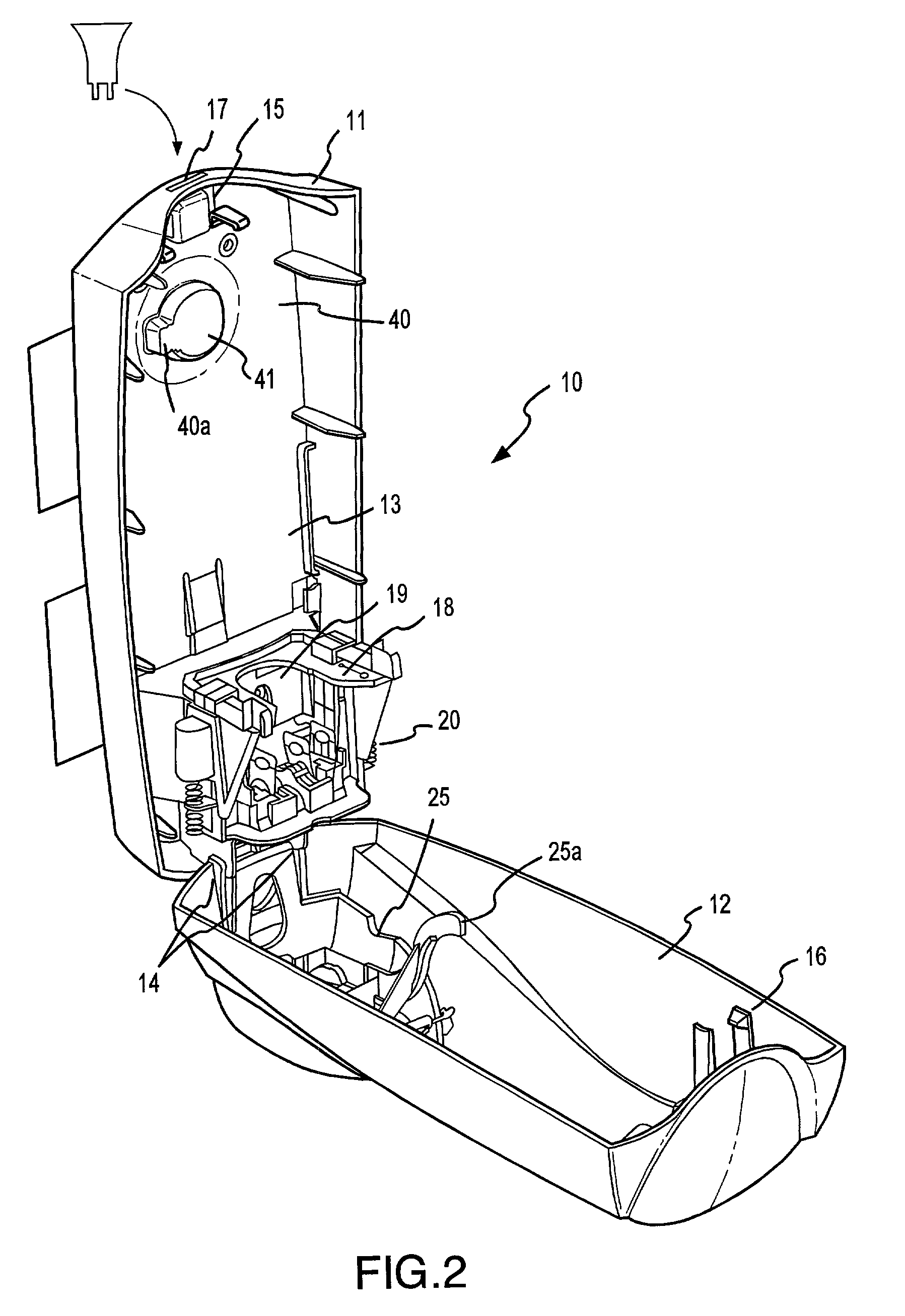
[0019] In general, the present invention comprises a liquid dispensing unit 10 with a backing 11, a cover 12, and a bottle 30. Dispensing unit 10 is preferably comprised of a substantially rigid plastic such as high density polyethylene ("HDPE"), but any other ...


PUM


Abstract

In accordance with various aspects of the present invention, a liquid dispensing apparatus having improved sanitary, aesthetics and stabilizing aspects is provided. For example, in accordance with one aspect of the present invention, liquid dispensing apparatus comprises a dispensing housing designed to contain a soap filled bottle. Depending on particular configurations, the housing may be designed as an open or closed system. In any case, the housing has a sleek, streamlined design with a dispensing button which tends to have a rounded appearance that accents the shape of the remainder of housing. In accordance with various other aspects of the present invention, within the housing is a stabilization system which prevents bottles which are not designed to engage housing from being inserted into housing. In addition to (or alternatively) housing may have support structure which allows the soap bottle to rest within housing with less of a propensity to wobble.

Description

[0001] 1. Technical Field of the Invention[0002] This invention relates generally to liquid dispensing devices, and more particularly, to liquid soap dispensing devices.[0003] 2. Background of the Invention[0004] Various liquid dispensing devices are known in the art. For example, commonly known dispensers are those used for distributing soap (e.g., hand soap) in public restrooms. The dispensers offer the benefits of convenience of use, easy refilling, refillable or disposable containers, and the like.[0005] One example of common soap dispensers is the disposable pump and container system which generally comprises a plastic bottle with a pump which screws into a cap fitted to the bottle. Generally, these units are disposed of once empty. However, in some cases, the bottles may be refilled. Unfortunately, however, these dispensers are susceptible to being knocked over, stolen, or lost because, in general, they merely sit on countertops and in wash basin areas. Further, the containers...

Claims


Application Information

Patent Timeline
Patent Type & Authority Applications(United States)
IPC IPC(8): A47K5/12A47K5/13B67D7/84
CPCA47K5/12
Inventor DEKONING, PAUL W.KNAUB, DAVE
Owner HENKEL IP & HOLDING GMBH
Learn More