Information-related devices and methods

a technology applied in the field of information-related devices and methods, can solve the problems of difficult to detect interference, and difficult to produce patterned writing surfaces, so as to achieve simple distinction, less interference, and less complex

Inactive Publication Date: 2002-03-21
ANOTO AB
View PDF0 Cites 21 Cited by
  • Summary
  • Abstract
  • Description
  • Claims
  • Application Information

AI Technical Summary

Benefits of technology

0023] It may also advantageous that information is coded in different patterns since this may entail simple distinguishing between different types of information such as distinguishing between position information and other information that can be descriptive of the product to which the coding pattern is applied.
0024] However, in the related art, because each position is typically coded with a complex symbol, recognition of many different elements is required, which make position coding sensitive to interference. According to the present invention, the value of a symbol is specified by the location of a marking in relation to a raster point. Thus, there is one type of symbol for each value. Therefore, a device that reads, determines positions, and decodes information only needs to detect one marking and does not need to differentiate between different elements (such as the different lines in a bar code) in order to determine the value of the symbols. Detection thus becomes simpler and less sensitive to interference.
0025] As mentioned above, in the related art, each position may be coded with a single symbol, which, therefore, must be rather complex. According to the present invention, each position may be coded with a plurality of symbols. Each individual symbol can thus be made less complex and simpler to detect with greater reliability. Furthermore, in the related art, each position may be coded with a symbol that is "isolated" from the symbols of surrounding positions. This may limit the position resolution of the surface occupied by the symbol for a position. The position-coding pattern according to the present invention can be made up in corresponding manner where each position is coded by an "isolated" group of symbols. However, in a preferred embodiment of the invention, each symbol may contribute to the coding of more than one position. In this manner, a "floating" transition between different positions may be created. In other words, each position may be coded partly by the same symbols as the adjoining positions. Floating coding may be advantageous since it may increase position resolution. Furthermore, it is possible to reduce the relationship between, on the one hand, the number of symbols which a position-determining device must register to carry out a position determination reliably and, on the other hand, the number of symbols which code a position.
0026] In a preferred embodiment, each symbol may contribute to the coding of both a first and a second position coordinate. Thus, different symbols are not necessarily needed for the different coordinates, which may make the position code simpler and the position resolution better. The coordinate system can be suitably Cartesian but other types of coordinate systems are also conceivable.

Problems solved by technology

Generally, the smaller the symbols are, the more difficult it is to produce the patterned writing surface and the greater the risk of incorrect position determinations.
On the other hand, the larger the symbols are, the worse the position resolution.

Method used


Image

  • Information-related devices and methods
  • Information-related devices and methods
  • Information-related devices and methods

Examples


Embodiment Construction

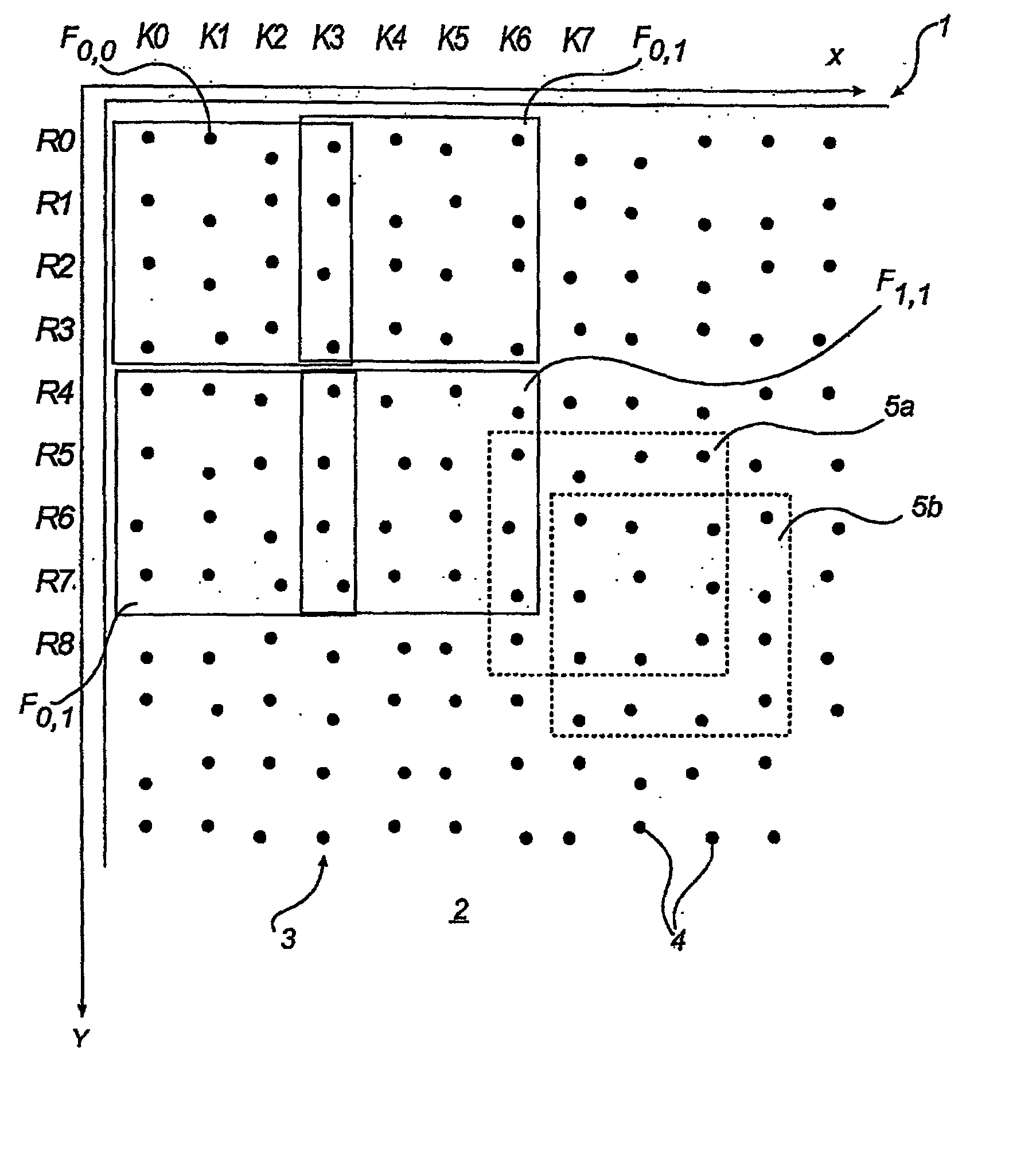
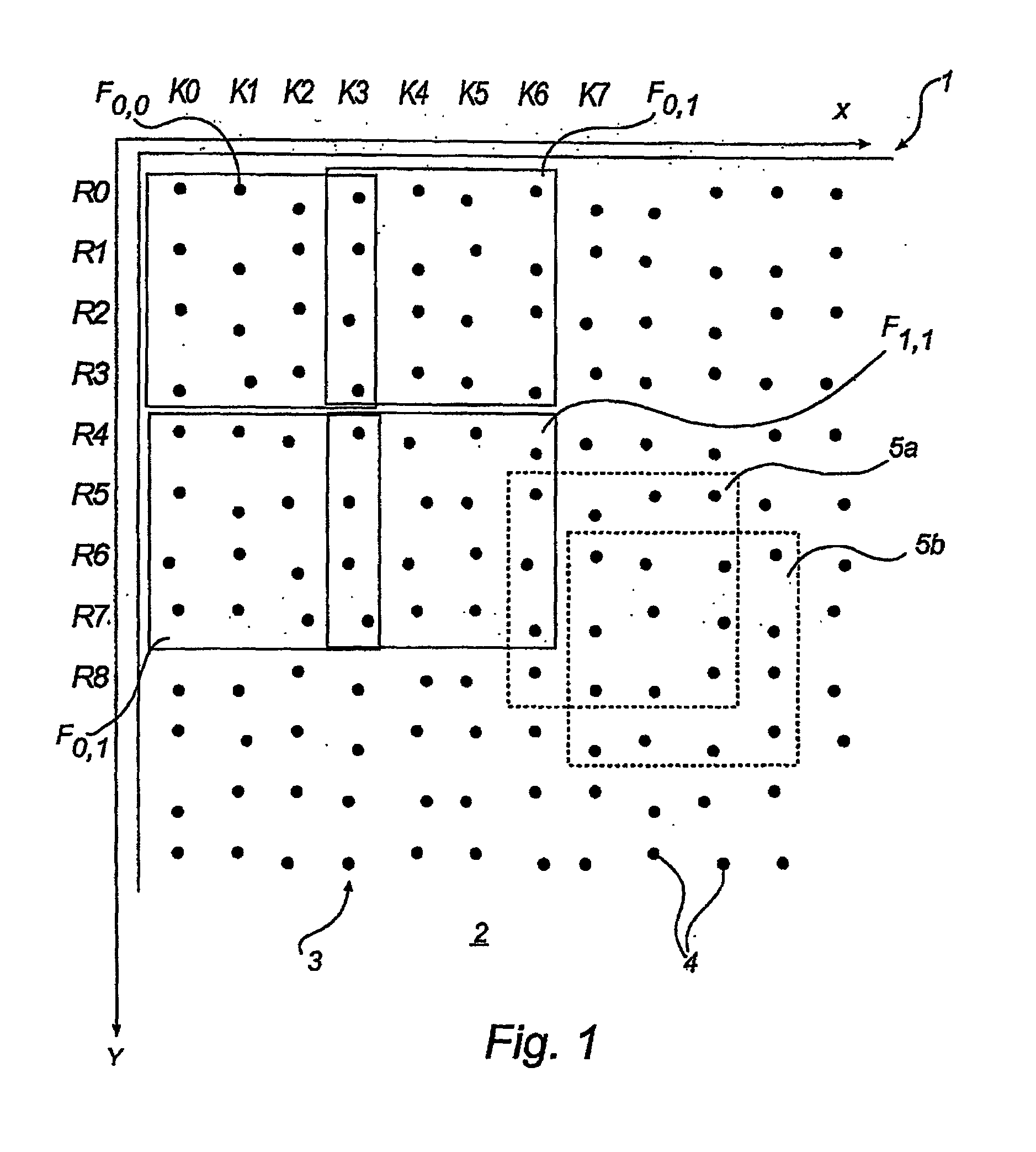
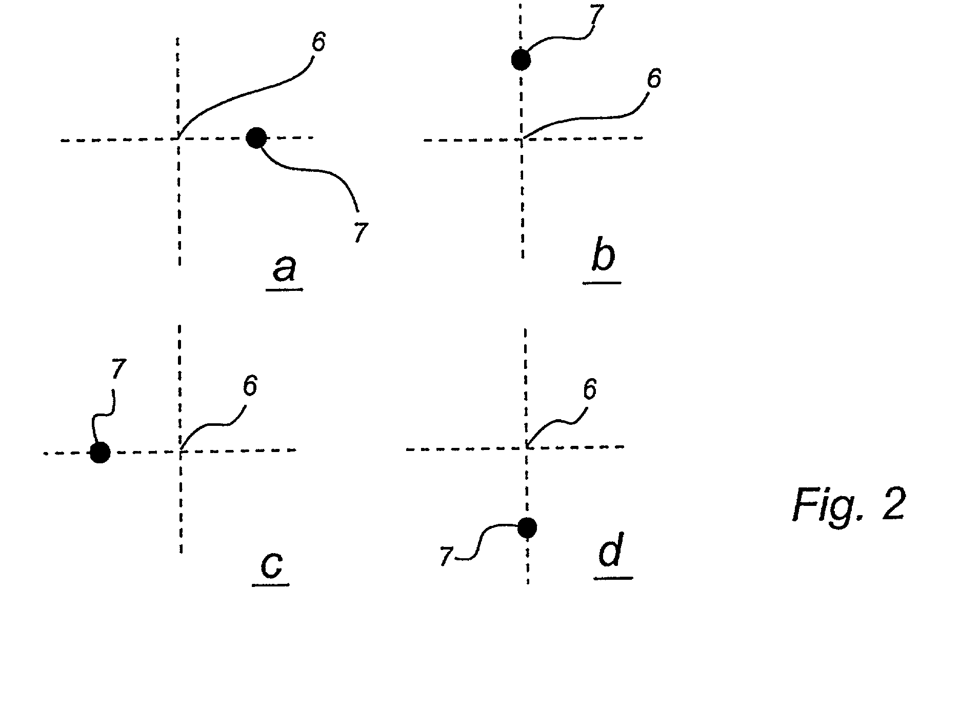
[0018] A first aspect of the invention may include a product which has a surface provided with a first coding pattern and a second coding pattern. The coding patterns may include symbols, which each represent at least two different values. Each symbol in the first coding pattern may be defined by a first raster point and at least one first marking, the first raster point being included in a first raster, which extends over the surface. Each symbol in the second coding pattern may also be defined by a second raster point and at least one second marking, the second raster point being included in a second raster. The second raster may be displaced in relation to the first raster and may also have a different spatial scale than the first raster. In a preferred embodiment, each symbol in the first and the second coding pattern may have a value that is indicated by a location of the first and second marking of the symbol in relation to the first raster point and the second raster point, r...


PUM


Abstract

A product has a surface provided with a first coding pattern and a second coding pattern. The coding patterns may include symbols each of which represents at least two different values. Each symbol in the first coding pattern may be defined by one raster point and at least one marking, the raster point being included in a first raster, which extends over the surface. Each symbol in the second coding pattern may also be defined by one raster point and at least one marking, the raster point being included in a second raster. This second raster may be displaced in relation to the first raster and may have a different spatial scale than the first raster. Each symbol in the first and the second pattern may have a value which, for example, can be indicated by the location of the marking belonging to the symbol in relation to a raster point in the first and second raster, respectively.

Description

Cross-Reference to Related Applications[0001] This application claims priority benefits based on Swedish Patent Application No. 0001235-1, filed Apr. 5, 2000, and U.S. Provisional Application 60 / 210,647, filed Jun. 9, 2000, the technical disclosures of both of which are hereby incorporated herein by reference.[0002] The present invention relates to an apparatus and method for determining a position on a surface containing a coding pattern.[0003] In many situations it is desirable to determine an absolute position on a surface. For example, it may be desirable to determine a position on a surface when recording and digitizing a document such as a drawing or map. It may also be desirable to determine a position of a surface when creating an electronic version of handwritten information.[0004] In these and other situations where position-determination is carried out, it is often desirable to have a computer program, in cooperation with an input device, carry out position-determination ...

Claims


Application Information

Patent Timeline
Patent Type & Authority Applications(United States)
IPC IPC(8): G06F3/03G06F3/033G06K7/14G06K19/06
CPCG06F3/0317G06F3/03545G06K7/14G06K19/06037G06F3/0321
Inventor WIEBE, LINUS
Owner ANOTO AB
Why Eureka
Try Eureka