
Road condition monitoring system

a condition monitoring and road technology, applied in the direction of photometry using electric radiation detectors, optical radiation measurement, instruments, etc., can solve the problems of difficult detection of water and ice by drivers or current synthetic vision systems, unusually difficult detection of clear ice (black or glaze ice) and increase the safety of motor vehicles

Active Publication Date: 2020-04-14
RGT UNIV OF MICHIGAN
View PDF131 Cites 2 Cited by
  • Summary
  • Abstract
  • Description
  • Claims
  • Application Information

AI Technical Summary

Benefits of technology

The present patent provides a simple way to identify different road conditions, including wet roads, icy roads, and dry roads. This information can be used to alert drivers, improve car control systems, and gather data for autonomous vehicles. The monitoring of road conditions increases safety for drivers and provides useful information for vehicle control and maintenance. This technology can also be shared with other connected vehicles and users.

Problems solved by technology

From these crashes, on average, nearly 6,000 people are killed and over 450,000 people are injured.
Water and ice can often be difficult to detect by drivers or current synthetic vision systems.
Clear ice (black or glaze ice) is unusually difficult to detect.
Unfortunately, practical systems capable of reliably detecting ice or water on roads do not exist.
Cars, trucks, trains, automated people movers, rails, monorails, metros, buses, motorcycles, bicycles and other similar vehicles lack suitable systems for detecting the presence of ice or water on surfaces, such as roadways, bridges, railways, sidewalks, or even runway and taxiways (such as in connection with ground operations of aircraft or supporting personal and vehicles).
However, unfortunately, temperature is not a reliable indicator of the presence of surface ice that may affect the safety or drivability of a vehicle.
The fact that drivers and operators are frequently unaware of the deteriorating road condition ahead of a vehicle frequently leads to accidents.
In fact, reflections by wet and / or oily surfaces and even smooth asphalt also cause polarization, which would lead to false reporting of the presence of ice.
Therefore, polarization measurements are not enough for distinguishing among the possible types of dielectric materials scattering or reflecting light.
Consequently, they cannot be used to detect the presence of ice or water unambiguously.
However, again, this system is unable to discern whether the detected polarization is due to ice or some other reflective material.
However, these prior art techniques are more complex and less accurate than the method described in the present disclosure.

Method used


Image

  • Road condition monitoring system
  • Road condition monitoring system
  • Road condition monitoring system

Examples


Embodiment Construction

[0029]Example embodiments will now be described more fully with reference to the accompanying drawings.

[0030]Example embodiments are provided so that this disclosure will be thorough, and will fully convey the scope to those who are skilled in the art. Numerous specific details are set forth such as examples of specific components, devices, and methods, to provide a thorough understanding of embodiments of the present disclosure. It will be apparent to those skilled in the art that specific details need not be employed, that example embodiments may be embodied in many different forms and that neither should be construed to limit the scope of the disclosure. In some example embodiments, well-known processes, well-known device structures, and well-known technologies are not described in detail.

[0031]The terminology used herein is for the purpose of describing particular example embodiments only and is not intended to be limiting. As used herein, the singular forms “a,”“an,” and “the” ...


PUM


Abstract

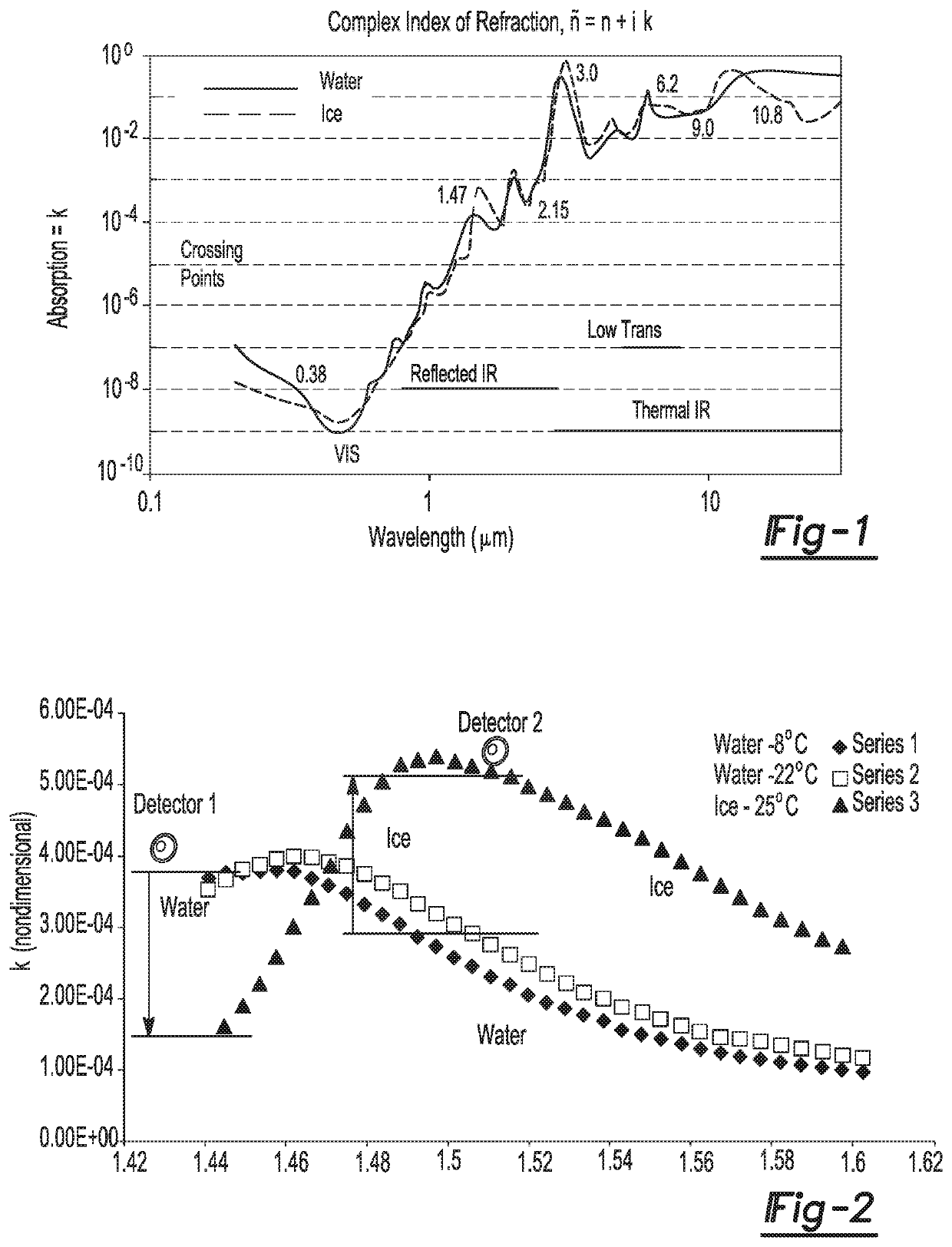
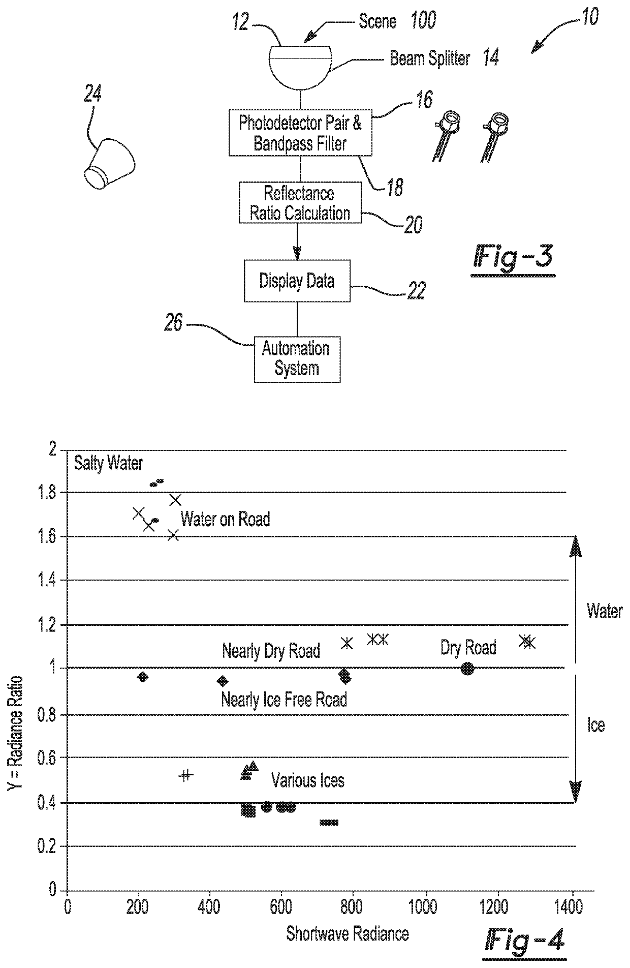
A road condition monitoring system capable of measuring the radiance reflected by an area of interest or the thermal radiance emitted by an area of interest in wavelengths range containing a crossover point between the curves representing the absorption of electromagnetic radiation by ice and water. A detector configured to measure the radiance in a first band having wavelengths in a spectral band on a first side of the crossover point and output a first band signal, and measure the radiance in a second band having wavelengths in a spectral band on a second opposing side of the crossover point and output a second band signal. A data processing unit configured to determine the ratio of the first band signal to the second band signal and compare the ratio to predetermined critical ratios to output a determination signal indicating the presence of water or various types of ice.

Description

GOVERNMENT INTEREST[0001]This invention was made with government support under IIP-1701057 awarded by the National Science Foundation. The government has certain rights in the invention.FIELD[0002]The present disclosure relates to a road condition monitoring system configured to detect water, snow, clear ice (also referred to as glaze or black ice), frost and other types of ices on roads or any other surface of interest. This system is configured to distinguish dry surfaces from those covered by water, clear ice, snow, and other types of ice.BACKGROUND AND SUMMARY[0003]This section provides background information related to the present disclosure which is not necessarily prior art. This section provides a general summary of the disclosure, and is not a comprehensive disclosure of its full scope or all of its features.[0004]Approximately 20% of all car crashes in the United States (nearly 1,250,000 per year) are weather-related. From these crashes, on average, nearly 6,000 people are...

Claims


Application Information

Patent Timeline
Patent Type & Authority Patents(United States)
IPC IPC(8): G01J1/42G01J1/04G08G1/0967
CPCG08G1/0967G01J1/0488G01J1/42G01N21/35G01J3/42G08G1/0112G08G1/0133G08G1/0141G08G1/09626G08G1/096791G08G1/096716G08G1/096725G08G1/165G01N21/31G08B19/02G01N21/94
Inventor RENNÓ, NILTON O.
Owner RGT UNIV OF MICHIGAN
Learn More