Assessing a network

Active Publication Date: 2011-10-25
BRITISH TELECOMM PLC
View PDF171 Cites 10 Cited by
  • Summary
  • Abstract
  • Description
  • Claims
  • Application Information

AI Technical Summary

Benefits of technology

Because test signals from the designated branch line can be distinguished from the signals from other branch lines, a feature in the test signal indicative of a loss or other fault can be associated with the designated branch line. In addition, because the phase of the test signals is modulated and this phase modulation detected interferometrically, the signals from the designated branch line can be more easily distinguished from signals from the other branch lines.
Preferably, the modulation will be imposed at a location such that the test signals can propagate in a downstream direction beyond this location (the downstream direction being a topological direction for signal flow that is away from the main line). Thus, the test signal will normally be returned from one or more regions or positions downstream of the location at which modulation occurs. This will make it easier to evaluate the position of a fault. If a branch line is an optical fibre, the modulation may be applied at a point along the fibre. Alternatively, the modulation may be applied at a fibre coupler, at a point along a path leading to the fibre.
A branch line may be designated in a selective fashion from a plurality of non designated branch lines. To make it simpler to distinguish signals from a selected line, branch lines may be selected one by one, in a sequential manner. A respective device for applying a modulation to each branch line may be provided, the devices each being responsive to an activation signal from actuation means, the actuation means being configured to transmit the activation signal to the device for the selected branch line. In one embodiment, the activation signal is a power signal for powering the selected device. However, the activation signal may be wireless signal such as a radio signal.

Problems solved by technology

However, the position of fault need not be evaluated.

Method used


Image

  • Assessing a network
  • Assessing a network
  • Assessing a network

Examples


Embodiment Construction

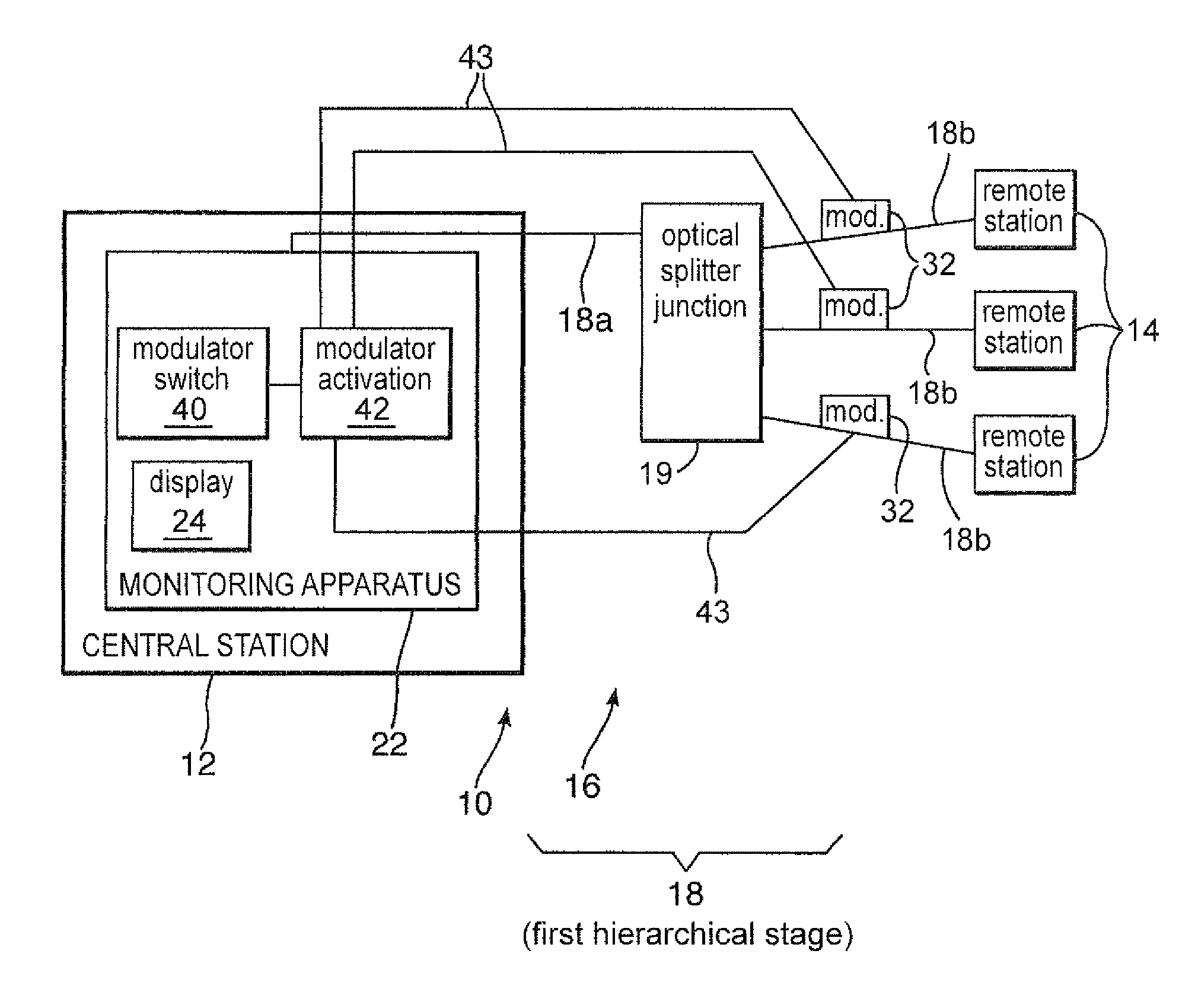
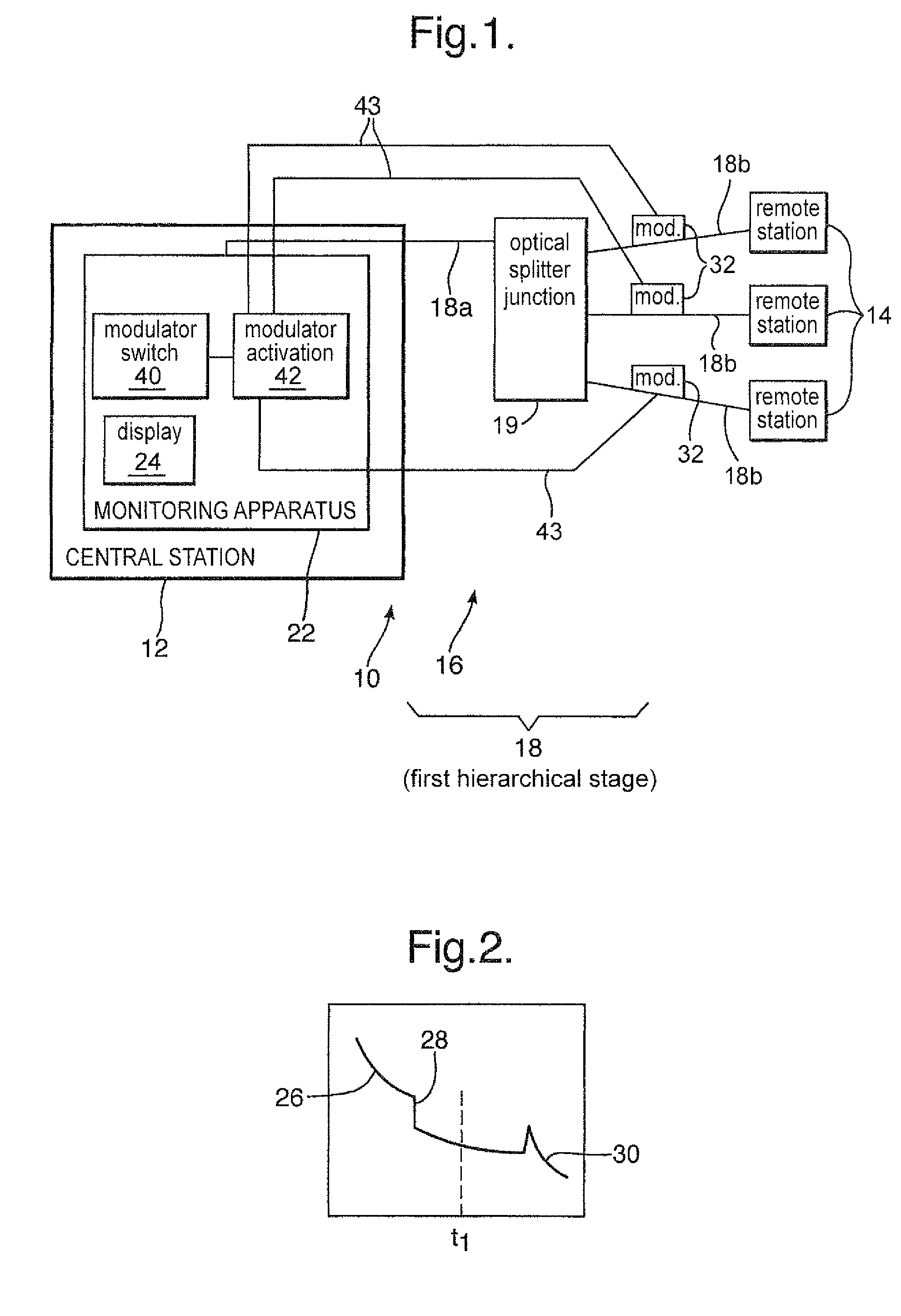
FIG. 1 shows an optical network 10 in which a central station 12 is connected to a plurality of remote stations 14 by an optical fibre system 16. The fibre system is arranged in an hierarchical fashion, such that for the first hierarchical stage 18, there is provided a main optical fibre 18a and a plurality of branch optical fibres 18b, the branch fibres 18b being connected to the main fibre 18a at a splitter assembly or other junction 19. Signals travelling along the main line 18a in the downstream direction, that is, away from the central station 12, are split at the splitter assembly 19 such that a portion of the signal intensity then continues along each of the fibres 18b. Likewise, signals travelling along the branch fibres 18b in the upstream direction, towards the central station 12, are combined or summed at the splitter 19, such that the signals from each branch fibre arriving at the same time at the splitter assembly travel along the main fibre together. The splitter assem...


PUM


Abstract

A network is assessed, in particular, a network having a main line and a plurality of branch lines. The method includes the steps of: (i) introducing test signals into the main line, the main line being coupled to the branch lines; (ii) imposing a modulation on test signals which propagate along the branch line, and (iii) monitoring test signals returned along the main line. The imposed phase modulation is detected interferometrically such that the test signals from the designated branch line can be distinguished with respect to the signals returned from other branch lines.

Description

This application is the US national phase of international application PCT / GB2005 / 004850 filed 15 Dec. 2005 which designated the U.S. and claims benefit of GB 0427734.9 and GB 0506591.7, dated 17 Dec. 2004 and 31 Mar. 2005, respectively, the entire content of which is hereby incorporated by reference.The present invention relates to the assessment of a network, in particular a network having a main line and a plurality of branch lines.BACKGROUND1. Technical FieldIt is known to assess a network having a main line and a plurality of branch lines by introducing a test signal into the main line and monitoring a return signal that arises due to the reflection or the backscattering of the test signal along the branch lines. An analysis of the return signal is performed to ascertain whether there are any faults or losses along the branch lines. However, if the return signal suggest a fault, it can be difficult to determine which branch line is responsible for the fault. In particular, as t...

Claims


Application Information

Patent Timeline
IPC IPC(8): G01B9/02G01N21/00H04B10/071
CPCH04B10/071H04B10/07H04B10/27H04L12/44
Inventor SIKORA, EDMUND S RHEALEY, PETER
Owner BRITISH TELECOMM PLC
Why Eureka
Try Eureka