However, there are certain limitations that exist with ATM that discourage the future use of this protocol within higher capacity switches.
The primary problems with ATM switches are the fixed sizes of ATM cells, too many
operating system interrupts that reduce peak speed, costly
network interface card, a 20% "
cell tax" overhead, signaling too slow for data (e.g., due to round trip path set-up and closure) and poor routing stability.
Without VC-based ATM in a conventional
system, it is nearly impossible to provide "hard QoS" or controlled
delay variation that is required for
toll quality two-way voice and video.
However, ER flow control is very difficult to design and to support the many to one joints in the VC mesh-type structure.
Such requirements are infeasible with today's conventional high speed switches.
Furthermore, the
scalability of the VC ATM-based switch is limited by the number of VC's available in ATM.
In particular, this characteristic limits the number of destinations ATM can set up.
As
the Internet grows, this limitation will create a serious limitation for ATM.
Furthermore, without the capability to join together on a certain
trunk VC's that are going toward the same destination, the size of a conventional network that can be supported is further severely limited.
The time to rebuild depends upon the
call setup rate of the switch technology and if that is not much faster than ATM
call setup is today, the rebuild time can become excessive and intolerable in conventional networks.
In addition, if the network 100 utilizes the synchronous optical network ("SONET") protocol, failure of a
trunk line results in the need for all traffic to be redirected from that
trunk, which typically results in a 50
millisecond outage.
Because of protocol complexity and because of the reliance upon
software implemented protocols for ATM switches, the
signaling protocol is too slow and the
virtual circuit ("VC") allocation is too low for conventional ATM switches to provide the necessary capacity for next generation services.
In addition, with
world wide web applications permeating all across
the Internet and Intranets, the signaling rates and VC counts are becoming far too high for current conventional ATM switches to be useful.
Thus, even though ATM's
protocol stack is currently viewed as superior to other protocol stacks, such as IP, ATM is becoming limited because it cannot compete with IP in cost to the user and in signaling capacity on the network backbone for the
network service provider.
However, conventional networks 100 utilizing TCP / IP as illustrated in FIG. 9 are very slow due to TCP flow control, the lack of availability of standard or hard QoS, the lack of Qos routing and the limitations associated with analyzing each packet for routing purposes.
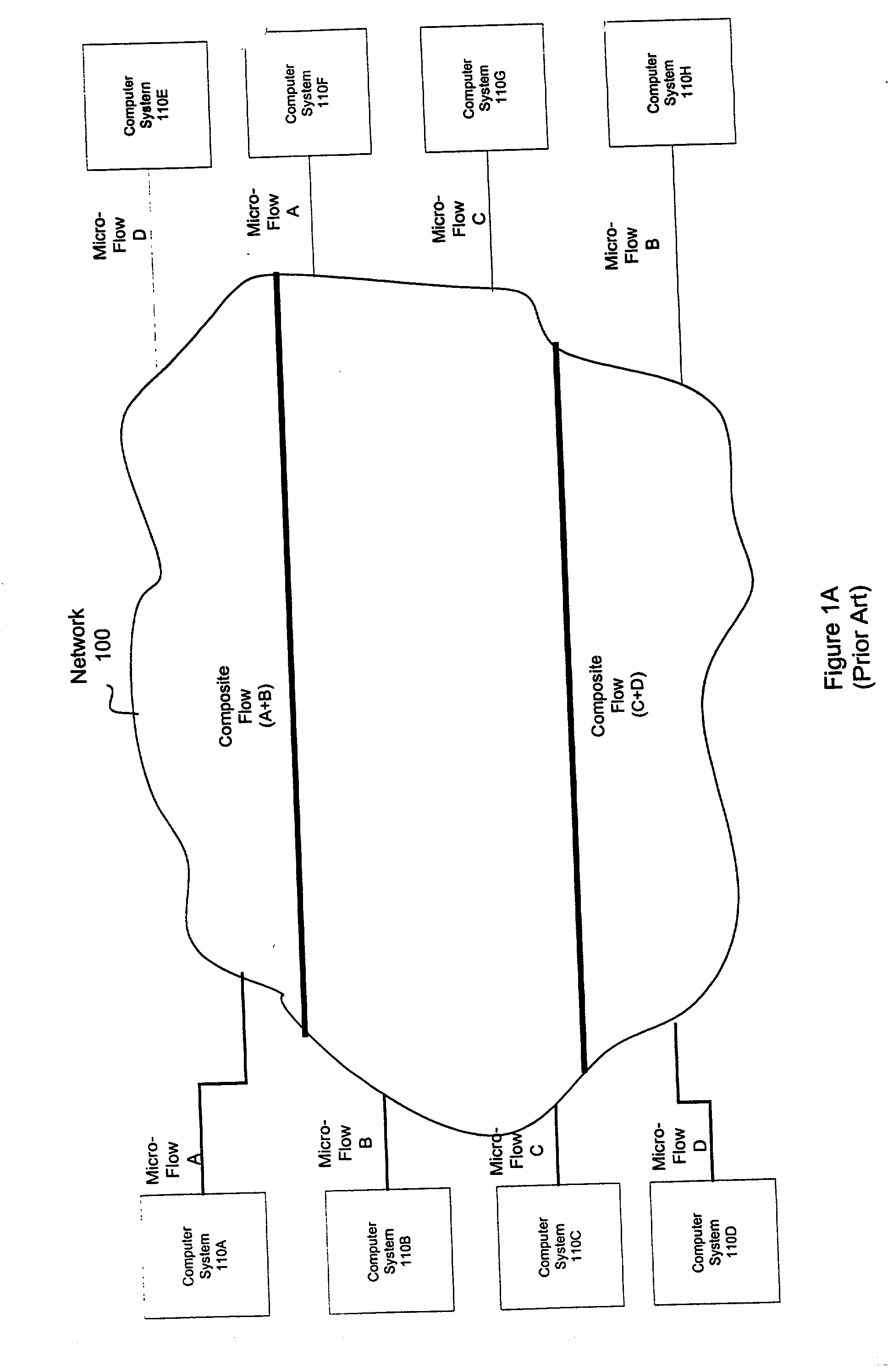
In particular, since conventional networks 100 cannot
route information based upon per-flow state information, conventional networks 100 are unable to
route each flow on a path with sufficient capacity.
This technique typically leads to the overloading of a specific
trunk line, thereby making QoS very difficult to implement.
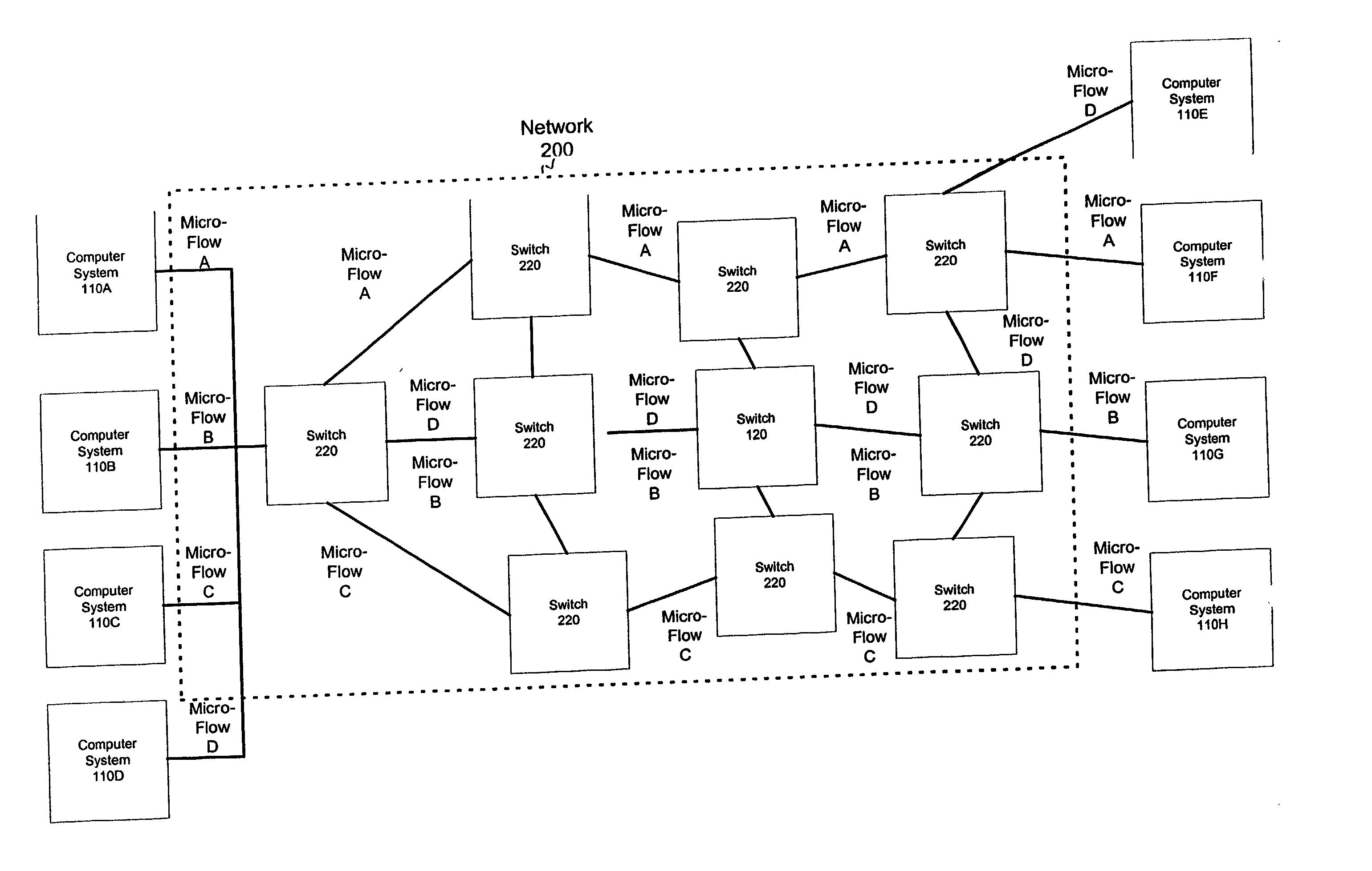
Without state information, a switch cannot identify which path each micro-flow should be sent over.
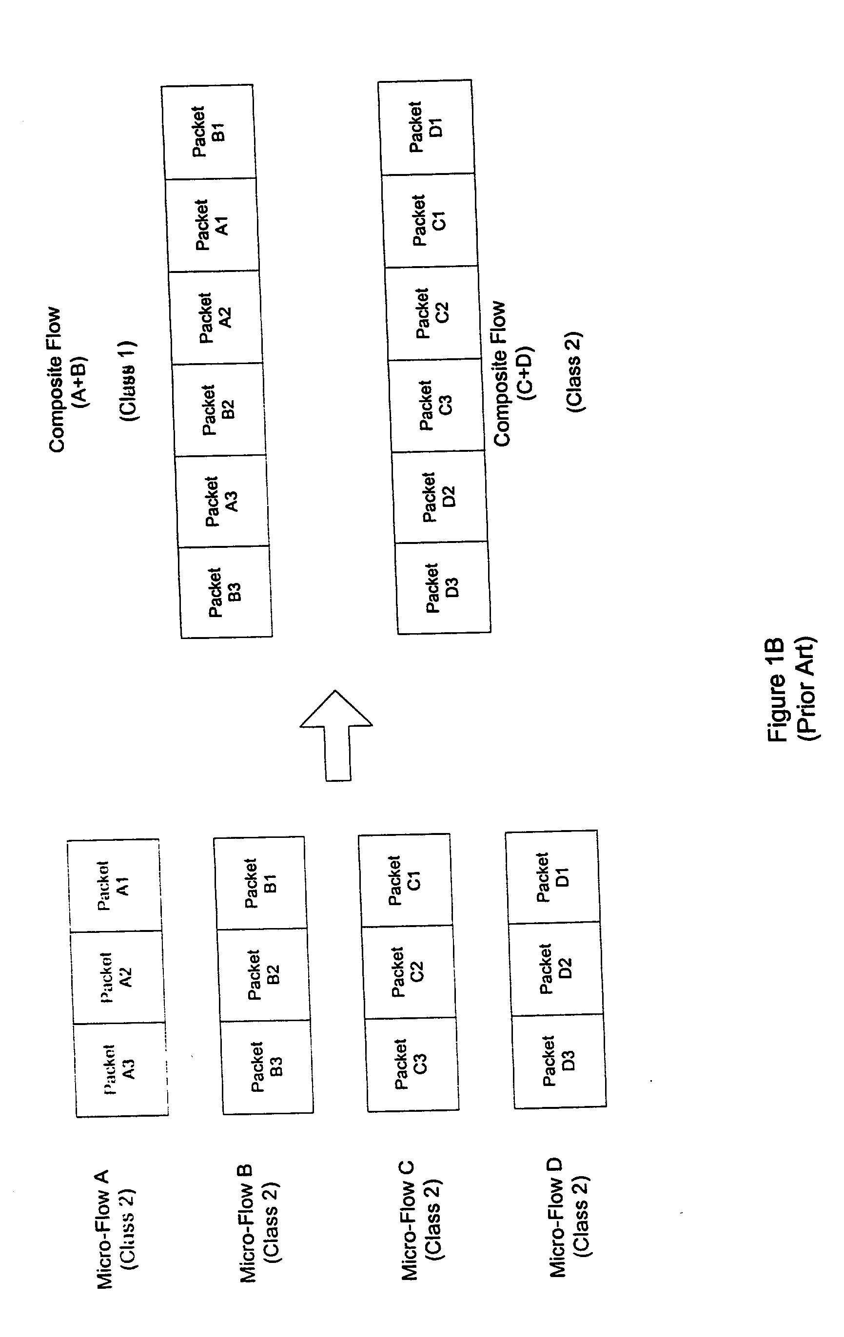
This limitation prevents the switch from splitting the composite flow into smaller micro-flows that can be routed over specific routes that have available capacity.
If all paths within a network 100 were fully loaded, conventional networks 100 also cannot discard packets from a specific micro-flow, thereby limiting the efficiency of the network 100.
As illustrated in FIG. 9, random early discards ("RED"), which are proportional to the buffer fill, can save the switch from becoming overloaded, but unfortunately results in wreaking havoc on the QoS of the transmission.
Without the capability of intelligent discarding, true QoS cannot be achieved.
Therefore, the switch cannot punish the misbehaving source, which thereby results in all flows suffering degradation as a result of the misbehaving source.
However, the complexity and
processing time involved with RSVP negotiation makes RSVP as poor as ATM for flow setup.
However, this protocol has significant limits that preclude DiffServ from providing an
effective solution to the problems faced with implementing QoS in an IP network.
There, however, are no QoS definitions to quantify each class, which thereby limits the QoS types that can be supported.
Since
the Internet will need to be able to carry a wide variety of QoS types, this quantification limitation greatly restricts the future use of DiffServ-based QoS in
large networks.
DiffServ in the IP context also does not allow each packet to be routed with state information associated with each packet.
However, such composite flows may far exceed the routing path's capacity.
In addition, without state information, multiple routes cannot be used because of packet ordering problems.
Within such a
queue, there would be no way to avoid head-of-line blocking.
Since the queues do not correspond to single micro-flows, weighted
fair queuing ("WFQ") cannot achieve an improvement in such factors as
delay variation.
Instead, WFQ in this context would result in further delaying traffic.
However, if one source (e.g., computer
system 110C) is transmitting at a much higher rate, this scheme causes major problems with regard to the ability to
route the higher
delay variance traffic.
Without keeping per micro-flow state information, WFQ techniques cannot minimize delay variation and cannot provide correction to the agreed rate at each switch.
Thus, delay variance cannot be kept constant and cannot be prevented from cumulating across the network.
The
disadvantage of this protocol, however, like DiffServ, is that the switch can only identify a small set of "standard" QoS patterns, thereby greatly restricting the future services available to a network 100 that requires a wide variety of QoS types to be used.
Furthermore, even though MPLS allows multiple composite flows on multiple routes, there still are restrictions on multiple paths.
Therefore, like DiffServ, when a path becomes overloaded, there is no way to reject new micro-flows or to split the composite flow into micro-flows and use alternative routes.

