
Gas-filled switching apparatus

a switching apparatus and gas-filled technology, applied in the direction of switchgear, high-tension/heavy-dress switch, metal casing arrangement, etc., can solve the problem of increasing the overall size of the sealed container, drying air has a lower dielectric strength, and it is not possible to install or remove the clips

Inactive Publication Date: 2002-05-30
MITSUBISHI ELECTRIC CORP
View PDF0 Cites 8 Cited by
  • Summary
  • Abstract
  • Description
  • Claims
  • Application Information

AI Technical Summary

Benefits of technology

[0018] In one preferred embodiment, a reinforcing plate is provided between the pressing member and either the cover or the flange so as to prevent abnormal deformation of the gasket by the clamping force of the pressing member.

Problems solved by technology

However, dry air has a lower dielectric strength than sulfur hexafluoride gas, so it is necessary to pressurize dry air to a higher pressure than required for sulfur hexafluoride to obtain a comparable dielectric strength.
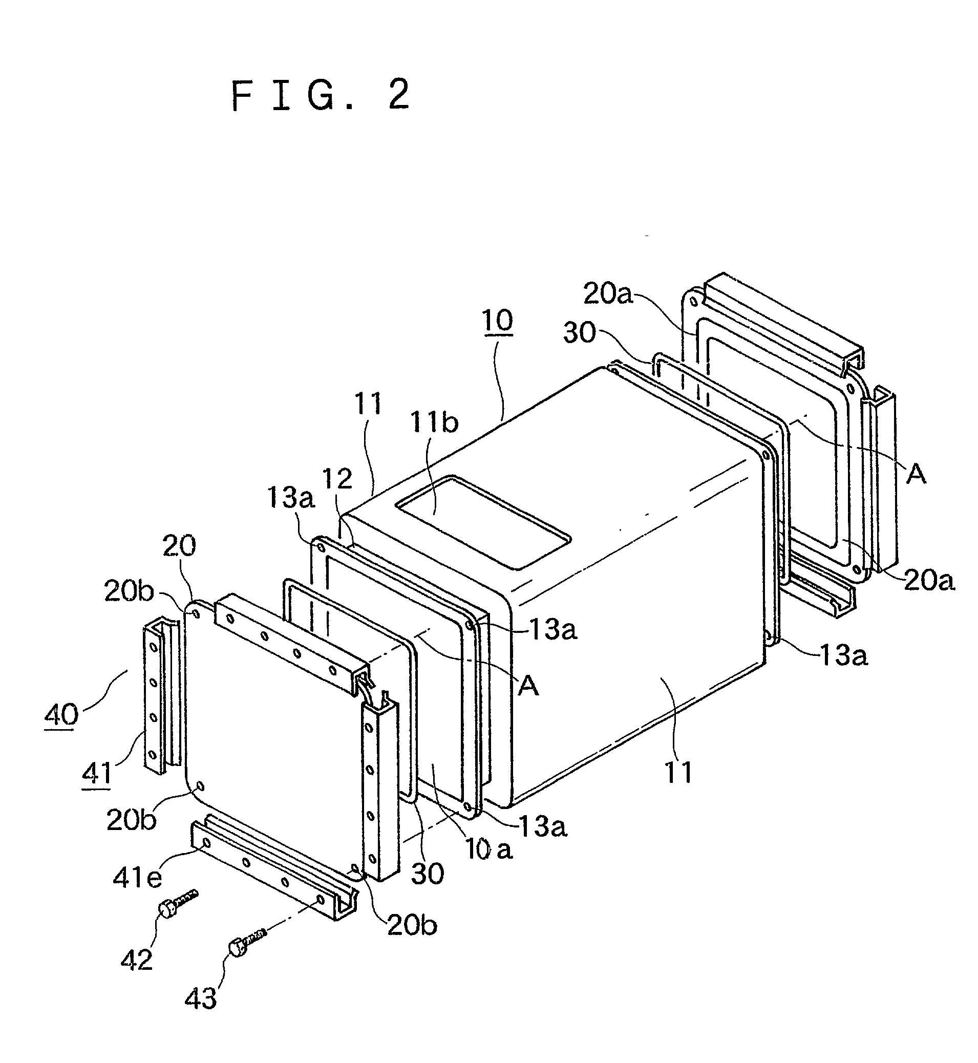
When bolts are used to secure a cover to a flange, the flange must be large enough to accommodate the bolts and bolt holes for receiving the bolts as well as the gasket groove, so there is the problem that the outer dimensions of the flange end up being large, which increases the overall size of the sealed container.
Due to these frictional forces, it is generally not possible to install or remove the clips by hand, and a special clip installation device is necessary for this purpose.
When a cubicle-type gas-filled switching apparatus is installed in a confined space, there may be insufficient room for the clip installation device to operate, making installation and repair difficult.

Method used


Image

  • Gas-filled switching apparatus
  • Gas-filled switching apparatus
  • Gas-filled switching apparatus

Examples


Embodiment Construction

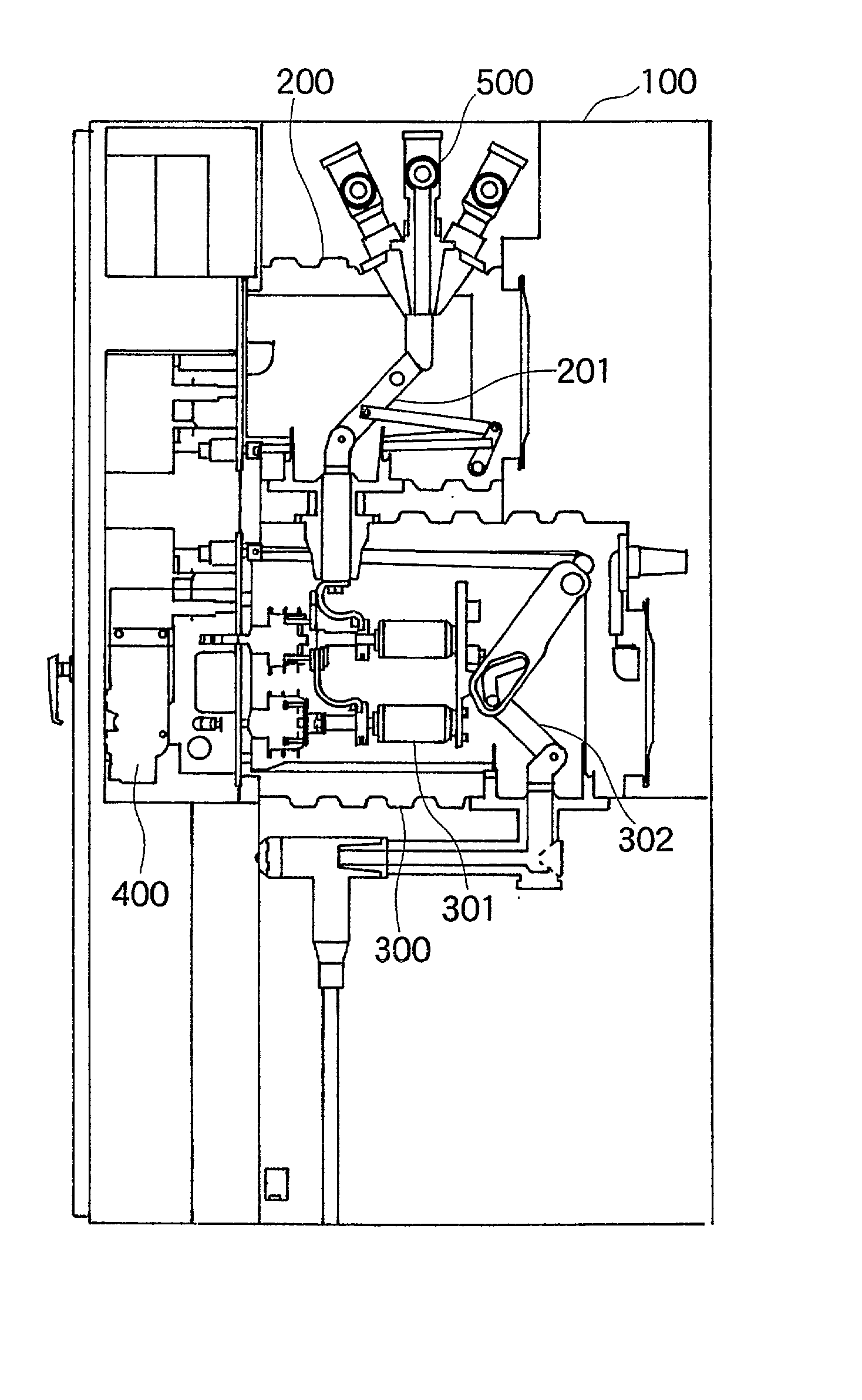
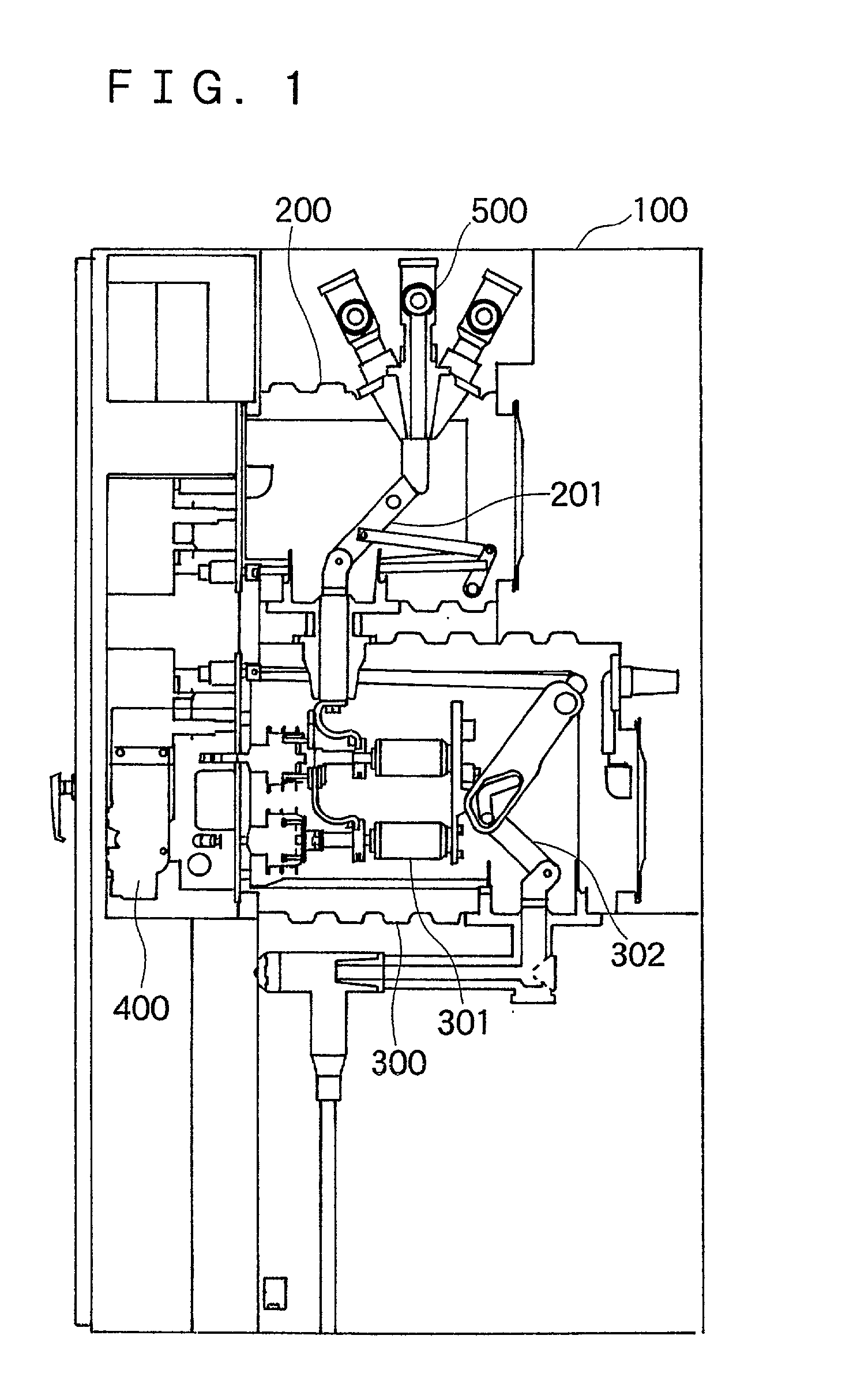
[0024] FIG. 1 is a schematic side elevation of the interior of an embodiment of a gas-filled switching apparatus according to the present invention. Parts which are the same as or correspond to those of the cubicle-type gas-filled switching apparatus of FIG. 5 are indicated by the same reference numerals. The illustrated switching apparatus performs switching between a live bus line 500 and a load. It includes a first sealed container 200 and a second sealed container 300 which are installed together with an operating portion 400 on the side surface of the interior of a metal box 100. A bus line side disconnecting switch 201 is housed within the first sealed container 200 and is connected to the bus line 500. A circuit breaker 301 is housed within the second sealed container 300 and is connected to the disconnecting switch 201. A load side disconnecting switch 302 is also housed within the second sealed container 300 and is connected to the circuit breaker 301.

[0025] FIG. 2 is an ex...


PUM


Abstract

A gas-filled switching apparatus has a gas-filled sealed container having a container body with a neck which surrounds an opening and a flange which extends outwards from the neck. A cover is disposed on the flange to cover the opening, and a gasket is disposed between the cover and the flange to form a seal around the opening. A plurality of clamps detachably secure the cover to the flange. Each clamp includes an adjustable pressing member exerting a clamping force on the cover and the flange.

Description

REFERENCE TO RELATED APPLICATIONS[0001] This application is based on Japanese Patent Application No. 2000-365414, filed in Japan on Nov. 30, 2000, the contents of which are hereby incorporated by reference.[0002] 1. Field of the Invention[0003] This invention relates to a switching apparatus for electric power filled with an electrically insulating gas. In particular, it relates to a gas-filled switching apparatus having an improved sealed container for housing switches or other components of the switching apparatus.[0004] 2. Description of the Related Art[0005] FIG. 5 is a schematic side elevation of a cubicle-type gas insulated switching apparatus of the type to which the present invention relates. Switches such as disconnecting switches 201 and 302, a circuit breaker 301, and a grounding switch 303 are housed in sealed containers 2 and 3 provided inside a metal box 1. An electrically insulating gas fills the sealed containers 2 and 3. The insulating breakdown voltage of the insul...

Claims


Application Information

Patent Timeline
IPC IPC(8): H01H33/02H02B13/02H01H33/56H02B13/045
CPCH02B13/045
Inventor NISHITANI, JUNICHIRO
Owner MITSUBISHI ELECTRIC CORP
Learn More