Rack boot

Inactive Publication Date: 2007-02-01
TOYODA GOSEI CO LTD
View PDF24 Cites 1 Cited by
  • Summary
  • Abstract
  • Description
  • Claims
  • Application Information

AI Technical Summary

Benefits of technology

[0012] The invention was made in view of the situations, and an object thereof is to provide a rack boot which can not only reduce the compression load but also avoid the abnormal deformation thereof.
[0020] In addition, the rack boot of the invention does not have a central bellows portion like the one of the rack boot of Patent Document No. 1 that has been described above. In addition, in at least the first bellows portion, the outside diameter of the ridge portions decreases gradually from the second cylindrical portion side where almost no deformation is produced even when the rack boot swings towards the first cylindrical portion side. The axial overall length of the folded bellows portion becomes shorter due to the outside diameter of the ridge portions decreasing gradually from the second cylindrical portion side towards the first cylindrical portion side. Consequently, even when the attaching region is largely contracted as has been described above, the axial overall length of the folded bellows portion is allowed to be accommodated within the attaching region. Due to this, there occurs no case where a buckling is produced in the bellows portion. Consequently, there is no chance of causing the drawback in which the buckled portion of the rack boot is held between the steering gearbox and the ball joint and the drawback in which the rack boot comes to interfere with various members which are disposed adjacent to the rack boot when the rack boot is compression deformed while swinging largely.
[0022] In the event that the rack boot of the invention includes the configuration described under (1) above, even in the second bellows portion, the ridge portions are not brought into press contact with each other, and hence, the compression load is reduced further. In addition, since the axial overall length of the folded bellows portion including the second bellows portion is made shorter, the buckling of the bellows portion can be avoided in a further ensured fashion.
[0024] In the event that the rack boot of the invention includes the configuration described under (3) above, the adjacent ridge portions are disposed in such a manner as to be spaced apart from each other in a diametrical direction (in a direction of the outside diameter of the rack boot). Consequently, when the rack boot is compression deformed while swinging largely, the drawback is avoided in the further ensured fashion in which the adjacent ridge portions are brought into press contact with each other, and consequently, the compression load is reduced sufficiently, the buckling of the bellows portion being avoided in the further ensured fashion.
[0025] In the event that the rack boot of the invention includes the configuration described under (4) above, the adjacent recess portions are disposed in such a manner as to be spaced apart from each other in the diametrical direction. Consequently, when the rack boot is compression deformed while swinging largely, the drawback is avoided in the further ensured fashion in which the adjacent recess portions are brought into press contact with each other, and consequently, the compression load is reduced sufficiently, the buckling of the bellows portion being avoided in the further ensured fashion.

Problems solved by technology

When the compression load imparted to the rack boot becomes too large, there is caused a drawback in which the steering feel of the steering wheel is deteriorated.
When the rack boot is buckled, there is caused a drawback in which the buckled portion of the rack boot is held between the steering gearbox 10 and the ball joint 173.
In addition, when the portion of the rackboot which is adjacent to the buckled portion projects largely towards the outer circumferential side thereof, the external shape of the rack boot is increased, and there is caused a drawback in which the rack boot comes to interfere with various members which are disposed adjacent to the rack boot.
Even with the rack boot that is disclosed in Patent Document No. 1, the drawback related to the buckling produced when the rack is compression deformed while swinging largely could not be eliminated.
Incidentally, when the attaching region becomes too small, an axial overall length of the folded bellows portion cannot be accommodated within the attaching region.
As is disclosed in Patent Document No. 1, even with the rack boot having the central bellows portion and the two tapered bellows portions, the buckling is similarly caused when the attaching region becomes too small.
In particular, in this case, a large buckling deformation is caused in the central bellows portion where the outside diameter is large.
Consequently, there is still caused the buckling in the rack boot disclosed in Patent Document No. 1, and the drawbacks attributed to the buckling of the rack boot still remain unsolved in which the buckled portion of the rack boot is held between the steering gearbox and the ball joint and the rack boot comes to interfere with various members which are disposed adjacent to the rack boot.

Method used


Image

  • Rack boot
  • Rack boot
  • Rack boot

Examples


embodiment 1

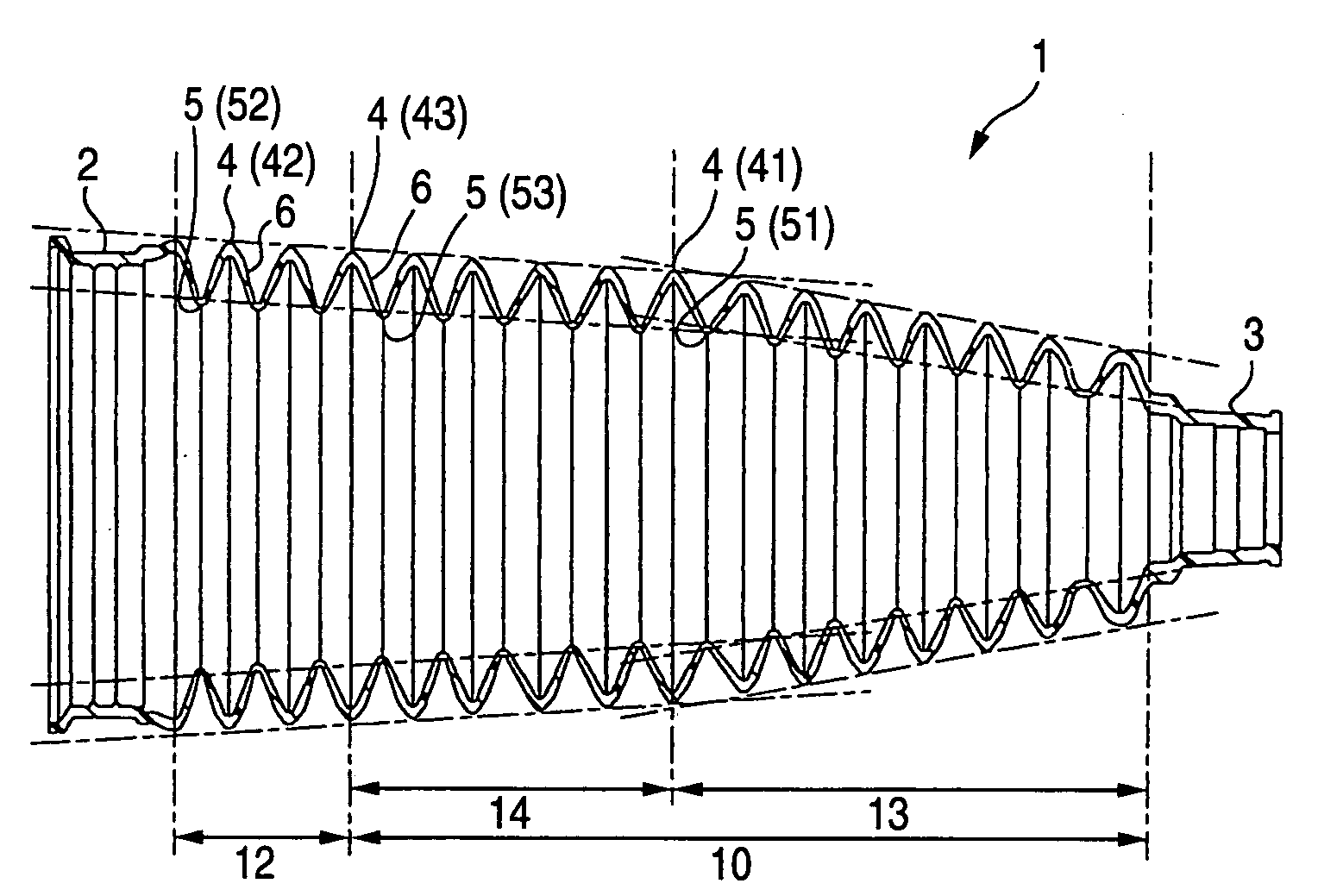
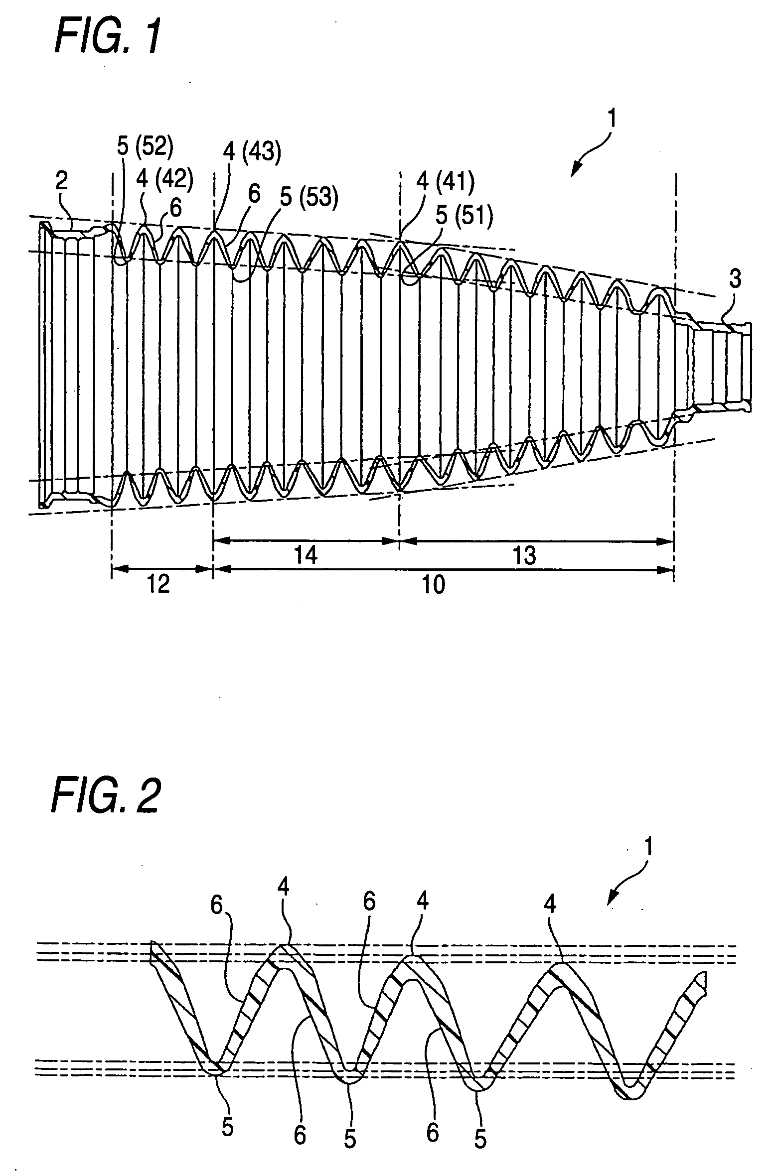
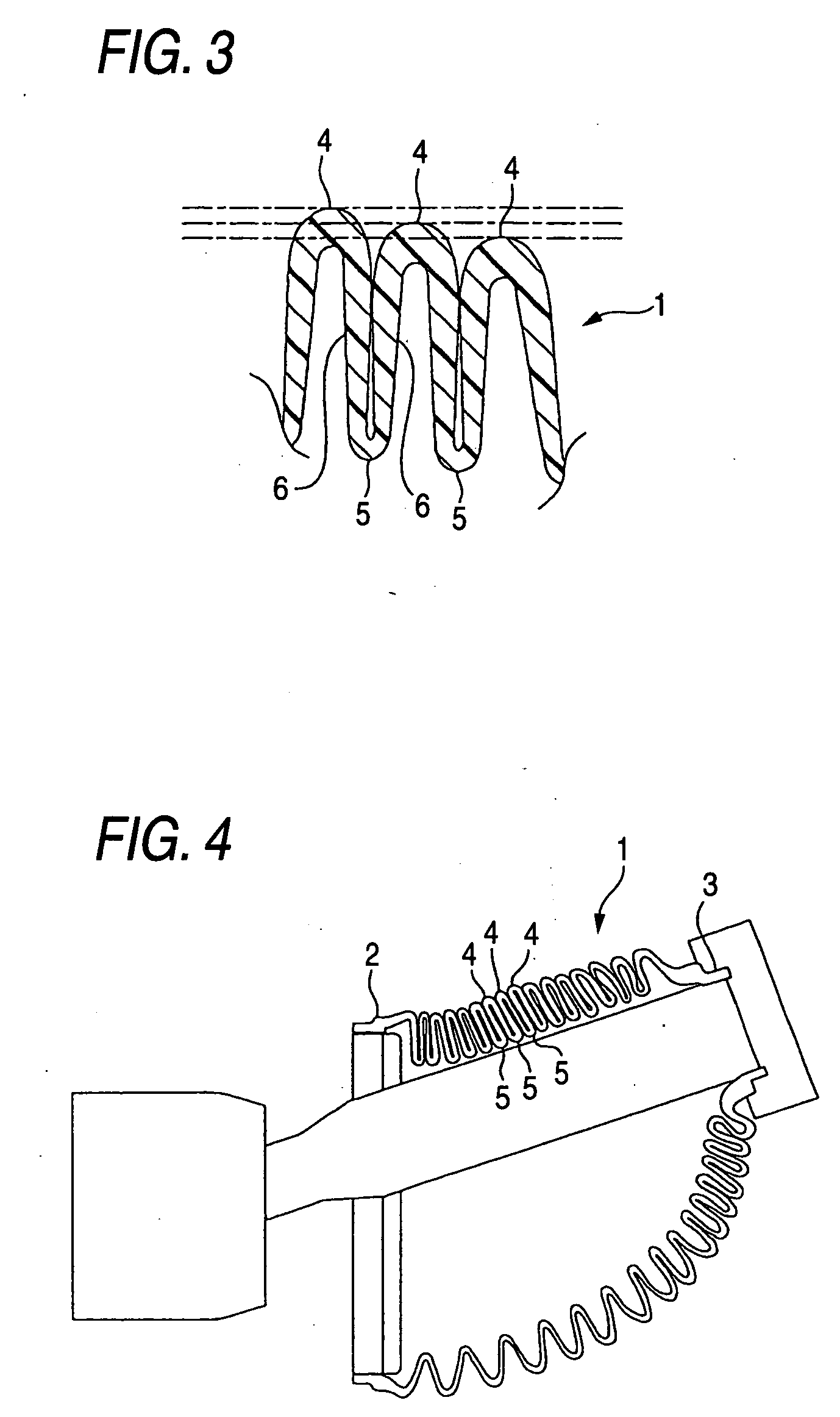
[0038] A rack boot of Embodiment 1 includes the configurations described under (1) to (4). An axially sectional view is shown in FIG. 1 which shows the rack boot of Embodiment 1, and an enlarged view of a main part of FIG. 1 is shown in FIG. 2. An explanatory view of the main part of the rack boot of Embodiment 1 is shown in FIG. 3 which shows exemplarily a state in which the rack boot is compression deformed in an axial direction thereof. An explanatory view is shown in FIG. 4 which shows exemplarily a state in which the rack boot of Embodiment 1 is compression deformed while swinging largely.

[0039] As shown in FIGS. 1 and 2, the resin boot of Embodiment 1 includes a bellows portion 1, a second cylindrical portion 2 and a first cylindrical portion 3. The bellows portion 1, the second cylindrical portion 2 and the first cylindrical portion 3 are formed integrally through blowmolding. The second cylindrical portion 2 is formed into a ring shape and is attached to a steering gearbox ...

embodiment 2

[0050] A rack boot of Embodiment 2 includes the configurations described under (2) to (4). An axially sectional view s shown in FIG. 5 which shows exemplarily the rack boot of Embodiment 2.

[0051] As shown in FIG. 5, the rack boot of Embodiment 2 includes a bellows portion 1, a second cylindrical portion 2 and a first cylindrical portion 3. The first cylindrical portion 3 and the second cylindrical portion 2 are the same as those of Embodiment 1. The bellows portion 1 is made up of a first bellows portion 10 and a second bellows portion 12. As with Embodiment 1, the first bellows portion 10 has a small diameter side bellows portion 13 and a large diameter side bellows portion 14. The small diameter side bellows portion 13 has a shape which is the same as that of Embodiment 1.

[0052] The large diameter side bellows portion 14 is formed into a tapered shape in which an outside diameter of ridge portions 4 is such that an outside diameter of the ridge portion 4 is made smaller than an ...


PUM


Abstract

In a rack boot having a bellows portion, a cylindrical portion which is formed at one end of the bellows portion so as to be fixed to a tie-rod and a second cylindrical portion which is formed at the other end of the bellows portion so as to be fixed to a steering gearbox, the bellows portion is divided into a first bellows portion which extends from a third ridge of ridge portions resulting when the ridge portions are counted from an end portion of the bellows portion which lies to the second cylindrical portion to the other end portion thereof which lies to the first cylindrical portion and a second bellows portion which extends from the third ridge to the end portion thereof which lies to the second cylindrical portion, and at least the first bellows portion is formed into a tapered shape.

Description

BACKGROUND OF THE INVENTION [0001] 1. Field of the Invention [0002] The present invention relates to a steering boot which is used on a motor vehicle. [0003] 2. Related Art [0004] A rack boot is a member which covers a ball joint between a steering gearbox and a tie-rod of a motor vehicle, and a general rack boot which is referred to as a rack boot or a steering rack boot is shown exemplarily in FIGS. 8 to 11, so as to describe the shape of the general rack boot below. FIG. 8 is an axially sectional view which exemplarily shows the general rack boot. FIGS. 9 and 8 are enlarged views of a main part of the general rack boot. FIG. 10 is an enlarged view of the main part of the general rack boot which shows exemplarily a state in which the general rack boot is compression deformed in an axial direction. FIG. 11 is an explanatory view which shows exemplarily a state in which the general rack boot is compression deformed while swinging largely. [0005] As shown in FIGS. 8 and 9, a rack boo...

Claims


Application Information

Patent Timeline
IPC IPC(8): B62D5/06
CPCB62D3/12F16J3/041B62D7/16
Inventor INAGAKI, HIDEHIKO
Owner TOYODA GOSEI CO LTD
Why Eureka
Try Eureka