Shield can

a shielding can and shielding technology, applied in the field of shielding cans, can solve the problems of small scratch marks on shielding cans, high logistic costs, and clear risks

Inactive Publication Date: 2002-06-27
OPTIS WIRELESS TECH LLC
View PDF0 Cites 3 Cited by
  • Summary
  • Abstract
  • Description
  • Claims
  • Application Information

AI Technical Summary

Problems solved by technology

This means that the shield can must be transported between the different manufactures to be handled in the different processes, causing high logistic costs.
Handling of the shield can in several moulds in different processes and locations causes tolerance problems.
Furthermore, the shield can is handled in at least two moulds and every time the shield can is ejected from a mould there is a clear risk that the shield can will get small scratch marks.
The above leads to a rather high rejection rate for shield cans manufactured according to the prior art, especially if the shield can is a cosmetic part, e.g. the back cover of a mobile telephone.

Method used


Image

  • Shield can
  • Shield can

Examples


Embodiment Construction

[0014] The term "electronic equipment" includes portable radio communication equipment. The term portable radio communication equipment includes all equipment such as mobile telephones, pagers, communicators, i.e. electronic organizers, smartphones or the like.

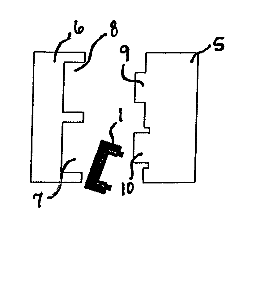
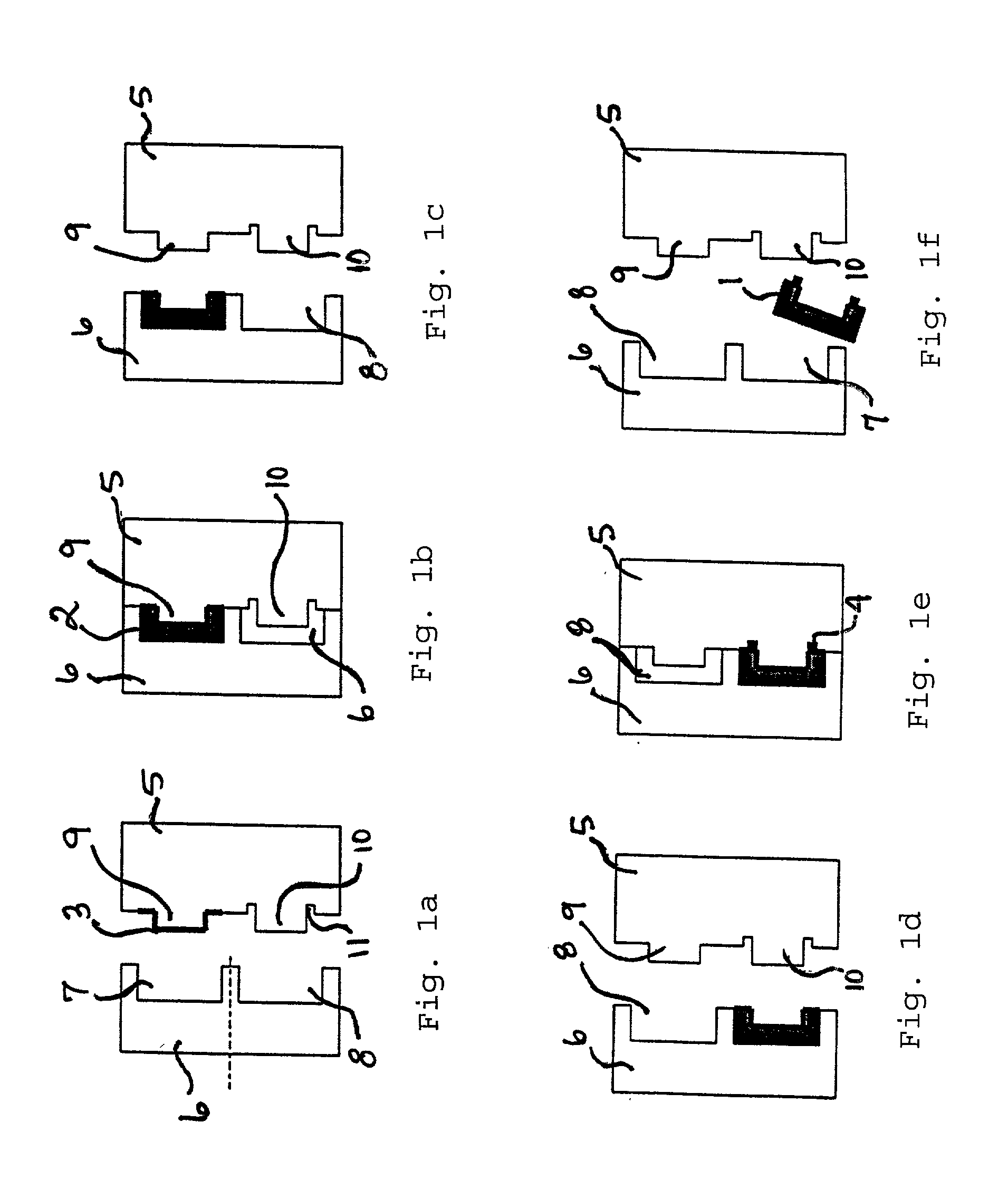
[0015] The shield can 1 of the present invention and as shown in the enclosed FIGS., comprises a plastic housing 2, a conductive inlay 3, placed in a recess of the plastic housing 2 and a conductive gasket 4 in electrical contact with the conductive inlay 3. In other embodiments (not shown) the conductive inlay is placed on the opposite side of the plastic housing 2.

[0016] The conductive inlay 3 is a foil, a cloth or the like. If a foil is used it will normally be made of a plastic comprising an electrically conductive layer. It is also possible to make the foil of a conductive material, having no separate layers. If a cloth is used it will at least partly have threads of a conductive material or threads covered by an electric...


PUM

PropertyMeasurementUnit
conductiveaaaaaaaaaa
electrically conductiveaaaaaaaaaa
elastomericaaaaaaaaaa

Abstract

The present invention concerns a method for the manufacture of shield cans and shield cans manufactured by said method. The shield cans comprising a plastic housing, a conductive inlay and a conductive gasket are manufactured by a multi-k procedure, preferably a 2-k procedure, in one single mold. The mold consists of a fixed mold part and a rotary mold part, having projections and recesses, respectively. The first step of the method is to place a preformed inlay on one projection and then forming the plastic housing on one side of the inlay. Then is the rotary mold part rotated, where after the gasket is formed on the side of the inlay opposite the housing.

Description

[0001] The present invention concerns shielding of electronic equipment, and more specifically a method of manufacturing shield cans utilized for such shielding. The shield can is used to protect electronic equipment from interfering radiation and is often a combination of a plastic housing, a conductive layer and a conductive gasket. The conductive layer is in electrical contact with a printed circuit board of the electronic equipment.STATE OF THE ART[0002] To protect electronic equipment against interfering radiation some kind of conductive shield is normally placed on or in connection with a printed circuit board of the electronic equipment. Such a shield functions also to reduce the risk that the electronic equipment itself disturbs other surrounding electronic equipment.[0003] A shield of this kind often has the form of a shield can comprising a plastic housing, a conductive layer on the inside of the housing and a conductive gasket. The conductive layer should be in electrical...

Claims


Application Information

Patent Timeline
Patent Type & Authority Applications(United States)
IPC IPC(8): B29C45/16H05KH05K9/00
CPCB29K2995/0011B29C45/1671
Inventor SANDEVI, TOMMYFAGRENIUS, GUSTAV
Owner OPTIS WIRELESS TECH LLC
Why Eureka
Try Eureka