Air bag device

a technology for air bags and bags, applied in acoustic signal devices, pedestrian/occupant safety arrangements, vehicle components, etc., can solve problems such as difficulty in operating switches and improper operation of switches

Inactive Publication Date: 2002-06-27
HONDA MOTOR CO LTD
View PDF0 Cites 23 Cited by
  • Summary
  • Abstract
  • Description
  • Claims
  • Application Information

AI Technical Summary

Benefits of technology

[0009] With the above arrangement, the ridge is formed on the inner surface of the cover member astride the tear lines to enhance the rigidity of the cover member. Therefore, when the cover member is pushed, it can be slid relative to the module-supporting member without being deformed, thereby properly operating the switch. The ridge protrudes from a back of the cover member and hence, the rigidity of the cover member can be enhanced, and an aesthetic appearance of the cover is not impaired. When the air bag is expanded to break the cover along the tear lines, the ridge provided astride the tear lines is also broken and hence, the air bag can be deployed without hindrance.
[0011] With the above arrangement, the groove is defined in the side of the ridge and connected to the bottom of the tear line and hence, when the tear lines are broken, the ridge can be broken reliably without reducing the normal rigidity of the unbroken cover member.
[0013] With the above arrangement, the reinforcing ribs are integrally formed on the inner surface of the cover member so that they do not intersect the tear lines, thereby enhancing the rigidity of the cover member. Therefore, when the cover member is pushed, it can be slid relative to the module-supporting member without being deformed, thereby properly operating the switch. When the air bag is expanded to break the cover along the tear lines, the reinforcing ribs, which do not intersect the tear lines, do not impede the breaking of the tear lines and hence, it is possible to deploy the air bag without hindrance. Moreover, the reinforcing ribs are formed on the inner surface of the cover member and hence, there is not a possibility that they would impair the aesthetic appearance of the cover.
[0015] With the above arrangement, at a least portion of the reinforcing ribs is formed to extend along the tear lines and hence, portions of the cover member in the vicinity of the tear lines are reinforced by the reinforcing ribs, and the rigidity of the cover member can be enhanced effectively.

Problems solved by technology

However, such arrangement of the switches is accompanied by a problem that it is difficult to operate the switches in a state in which the steering wheel has been turned from a neutral position.
For this reason, there is a possibility that only the portion of the cover member pushed by the fingers is depressed, whereby the entire cover member is not slid smoothly relative to the module-supporting member and as a result, the switches are not operated properly.

Method used


Image

  • Air bag device
  • Air bag device
  • Air bag device

Examples


first embodiment

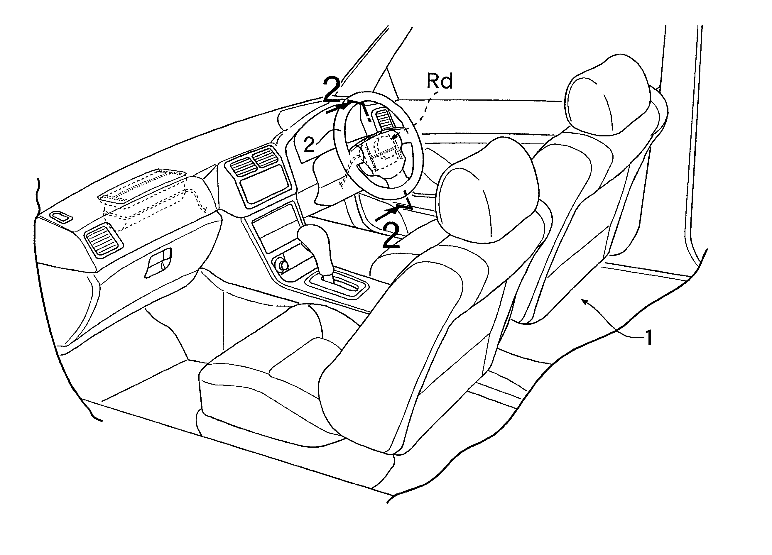
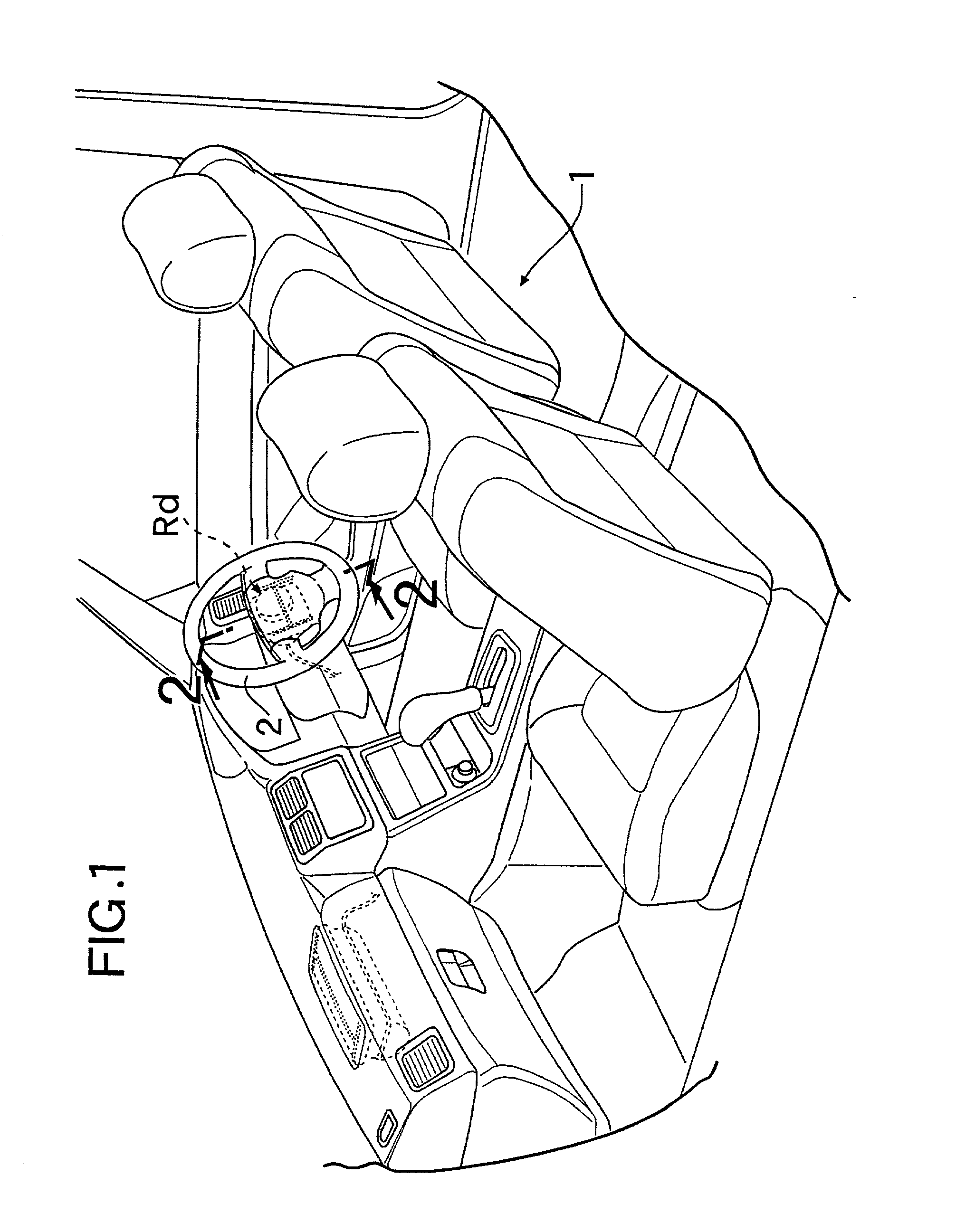
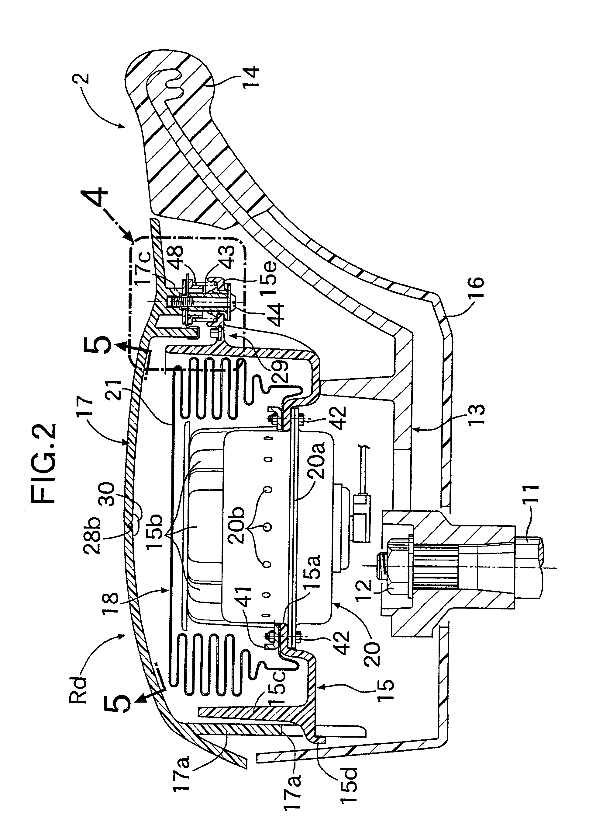
[0031] FIGS. 1 to 6 show the present invention. FIG. 1 is a perspective view of a front portion of a passenger compartment of an automobile; FIG. 2 is an enlarged sectional view taken along a line 2-2 in FIG. 1; FIG. 3 is an exploded perspective view of an air bag device for a driver's seat; FIG. 4 is an enlarged view of a portion indicated by arrow 4 in FIG. 2; FIG. 5 is a view taken along a line 5-5 in FIG. 2; and FIG. 6 is an enlarged sectional view taken along a line 6-6 in FIG. 5.

[0032] As shown in FIGS. 1 to 4, an air bag device Rd for a driver's seat 1 is mounted at a central portion of a steering wheel 2 disposed in front of the driver's seat 1. The steering wheel 2 includes a steering boss 13 relatively non-rotatably fitted over and fixed to a rear end of a steering shaft 11 by a nut 12, an annular wheel rim 14 disposed to surround the steering boss 13, a cup-shaped module-supporting member 15 fixed to a rear surface of the steering boss 13, a front cover member 16 covering...

second embodiment

[0038] the present invention will be described with reference to FIGS. 7 and 8.

[0039] In the second embodiment, the shapes of the ridges 30, 30 include flat upper and side surfaces, rather from curved surfaces as in the first embodiment. Also, grooves 30a, 30a having a V-shaped section are defined in laterally inner side faces of ridges 30, 30 to reach a bottom of a tear line 28b. The grooves 30a, 30a ensure that the ridges 30, 30 can be broken further reliably upon expansion of the air bag, with almost no change in the rigidity enhancing effect of the ridges 30, 30.

[0040] The third and fourth embodiments of the present invention will be described with reference to FIGS. 9A and 9B.

[0041] In the third embodiment shown in FIG. 9A, grooves 30a, 30a, similar to those in the second embodiment, are defined in laterally outer side faces of ridges 30, 30. The ridges 30 have the same basic shape as the ridges 30 of the second embodiment, except that the grooves 30 are in the laterally outer ...

fifth embodiment

[0043] the present invention will be described with reference to FIGS. 10 to 12.

[0044] The shapes of tear lines 28a to 28f formed in an inner surface of a rear cover member 17 are different from those in the first to fourth embodiments. Other H-shaped tear lines 28d, 28e and 28f are provided inside tear lines 28a, 28b and 28c corresponding to the tear lines 28a, 28b and 28c in each of the first to fourth embodiments. Further, two reinforcing ribs 32a and 32c are integrally provided in a projecting fashion to extend along laterally outer sides of the two vertically extending tear lines 28d and 28f, and are connected their lower ends to each other by a laterally extending reinforcing rib 32b, whereby the reinforcing ribs 32a, 32b and 32c are formed in a U-shape as a whole. In addition, the two vertically extending tear lines 28d and 28f are connected at their upper ends to each other by a single laterally extending reinforcing rib 32d.

[0045] Thus, even according to the fifth embodimen...


PUM


Abstract

An air bag device having a switch adapted to be operated when a breakable cover member covering an air bag module mounted in the steering wheel is pushed. Particularly, H-shaped tear lines, including grooves of a V-shape in section, are defined in an inner surface of the cover member. The tear lines are broken by a pressure resulting from the expansion of the air bag to open a lid defined in the cover member. A pair of ridges are integrally formed on the cover member astride a central one of the tear lines. The rigidity of the rear cover member is enhanced by the ridges, whereby the deformation of the cover member is prevented. Thus, the cover member can be slid smoothly to ensure the reliable operation of the switch.

Description

[0001] 1. Field of the Invention[0002] The present invention relates to an air bag device designed so that upon collision of a vehicle an air bag is deployed into a vehicle compartment through an opening resulting from the breaking of a cover member mounted on a steering wheel.[0003] 2. Description of Relevant Art[0004] There is a conventionally known air bag device in which an air bag module including an air bag and an inflator is accommodated in a central portion of a steering wheel, and a cover member in the steering wheel is broken by a pressure generated by the expansion of the air bag upon collision of a vehicle, thereby permitting the air bag to deploy into a vehicle compartment. In such air bag device, in order to reliably break the cover member by the pressure generated by the expansion of the air bag, a tear line comprising a brittle groove is formed in an inner surface of the cover member (surface opposed to the air bag module (see Japanese Patent Application Laid-open No...

Claims


Application Information

Patent Timeline
Patent Type & Authority Applications(United States)
IPC IPC(8): B60Q5/00B60R21/20B60R21/203B60R21/2165
CPCB60Q5/003B60R21/21656B60R21/2037
Inventor KAI, TAKESHISAKAI, TOSHIYASAITOH, HIROYUKISATO, MASAHIRO
Owner HONDA MOTOR CO LTD
Why Eureka
Try Eureka