Image processing apparatus and image sensing device

Inactive Publication Date: 2002-06-27
MINOLTA CO LTD
View PDF6 Cites 62 Cited by
  • Summary
  • Abstract
  • Description
  • Claims
  • Application Information

AI Technical Summary

Problems solved by technology

Consequently, where the amount of blur that is specified during blur control is large, for example, even though the image is only minimally affected even if the co

Method used


Image

  • Image processing apparatus and image sensing device
  • Image processing apparatus and image sensing device
  • Image processing apparatus and image sensing device

Examples


Embodiment Construction

[0025] An embodiment of the present invention is explained below with reference to the drawings.

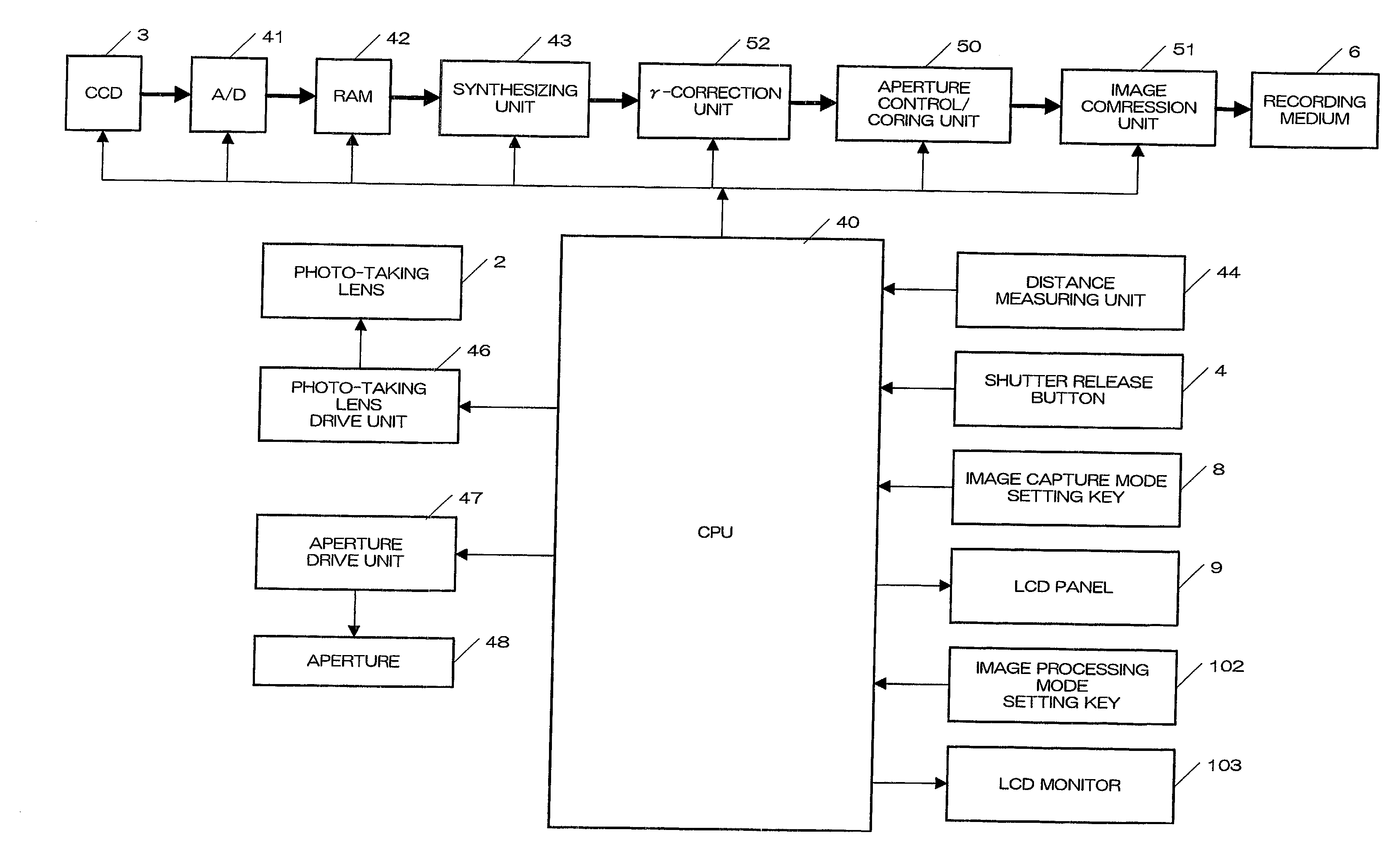
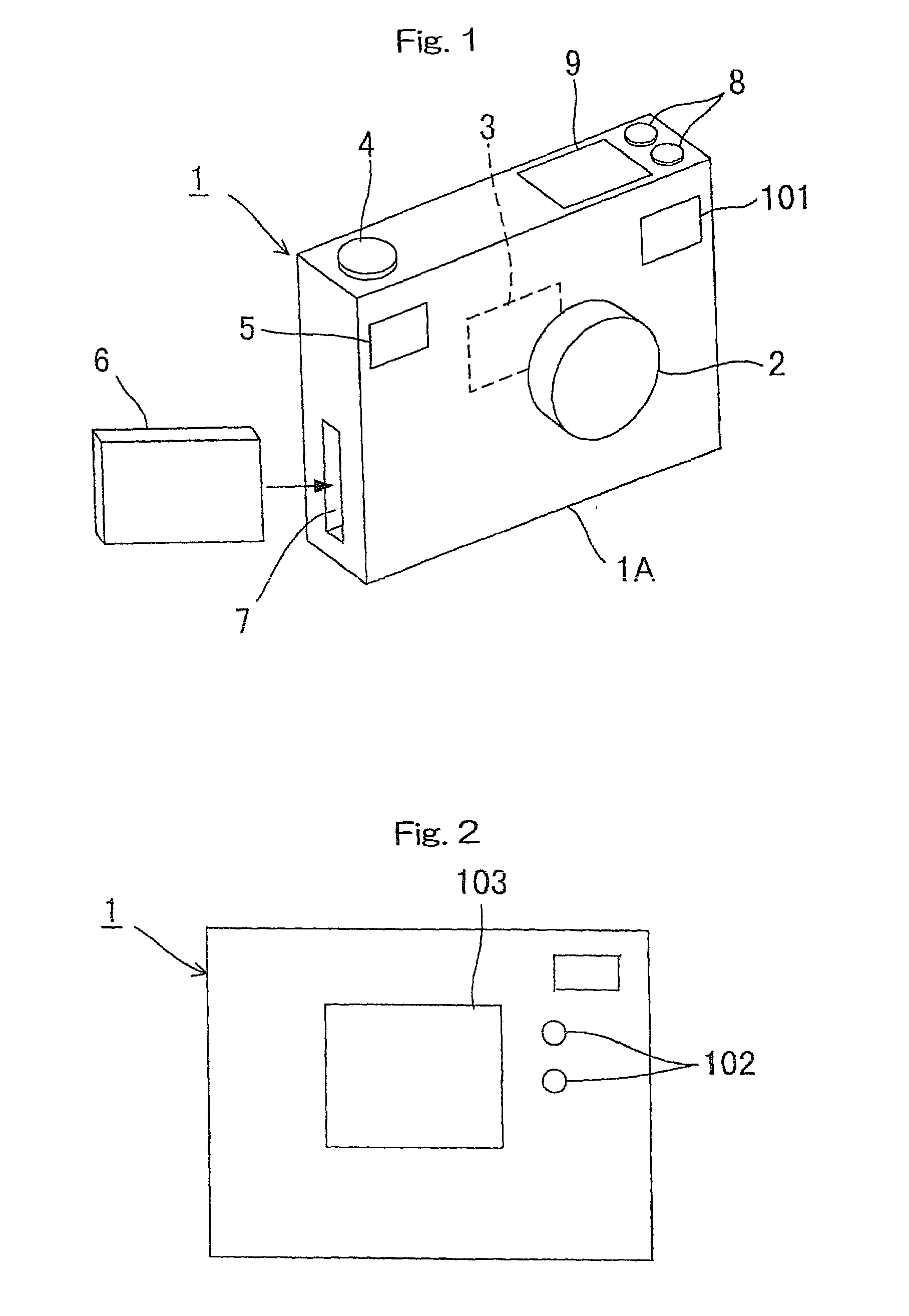
[0026] FIGS. 1 and 2 are an perspective external view and a rear elevation of a digital camera, which comprises the image sensing device that incorporates the image processing feature pertaining to one embodiment of the present invention.

[0027] In FIGS. 1 and 2, 1 is a digital camera, and on the front surface of the camera body 1A are located a photo-taking lens 2, a finder window 5, and a distance measuring window 101. Inside the camera body is located a CCD 3, which is a photo-sensing element that performs photoelectric conversion of the captured optical image, and which is located in the light path of the photo-taking lens 2. Furthermore, on the top surface of the camera body 1A are located a shutter release button 4, image capture mode setting keys 8, and a liquid crystal display panel 9. In these drawings, the number 6 indicates a recording medium in which the image data is stored, a...


PUM


Abstract

The image sensing device or image processing apparatus has a synthesizing capability enabling the device or apparatus to perform blur control using a specified amount of blur and to prepare a blur-controlled image, as well as a blur-controlled image processing capability enabling the device or apparatus to carry out processes other than blur control on the prepared blur-controlled image and to change the degree of processing in accordance with the amount of blur.

Description

[0001] This application is based on the application No. 2000-268813 filed in Japan, the content of which is hereby incorporated by reference.[0002] 1. Field of the Invention[0003] The present invention relates to an image processing apparatus that prepares blur-controlled images from images captured using an image sensing device, such as a digital camera, and an image sensing device incorporating this image processing feature.[0004] 2. Description of the Related Art[0005] Digital cameras have been proposed that capture multiple images focusing on the foreground or background, for example, and having different focal lengths, and that prepare from these multiple images blur-controlled images in which the degree of blurring of the objects, such as the foreground and background, is adjusted.[0006] A blur-controlled image may further undergo other processes, such as image compression, which is performed in order to store the image in a recording medium, coring or aperture control.[0007] ...

Claims


Application Information

Patent Timeline
IPC IPC(8): H04N1/387G06T5/00H04N1/407H04N1/41H04N5/14H04N5/232H04N5/262H04N5/77
CPCH04N5/232H04N5/772H04N5/262H04N5/23212H04N23/673H04N23/676
Inventor KITAMURA, MASAHIROMORIMOTO, YASUHIROFUJII, SHINICHI
Owner MINOLTA CO LTD
Why Eureka
Try Eureka