
Electronic parking meter system

Inactive Publication Date: 2002-08-15
FYBR
View PDF25 Cites 70 Cited by
  • Summary
  • Abstract
  • Description
  • Claims
  • Application Information

AI Technical Summary

Benefits of technology

[0045] More particularly, it is an object of the present invention to provide positive and accurate sensing of the presence or absence of a vehicle in a particular parking space within a given vehicle parking area.

Problems solved by technology

One problem with light beam detection is that the beam does not distinguish between a vehicle and any other solid object.
In addition, false activity could occur with the opening of a door or other movement in front of the meter sensor.
Even temperature or humidity changes could cause problems.
When any vehicle vacates the parking space the remaining time is lost; and the next arriving vehicle must purchase new time for the use of the parking space.
Further, the vehicle would not be able to purchase additional time for the space.
(1) Reset the digital parking meter to zero when the parking space is vacated, thus significantly increasing meter revenue in high demand situations. Independent research reveals that average revenue increase approximately 27% in high demand parking locations when using this technique.
(2) Prevent "meter feeding" by not posting additional time for over-limit payments until after the parking space has been vacated, thus forcing parking space turnover and, in effect, increasing overall parking capacity.
(3) Automatically allocate free time as the parking space is occupied. This will enable very short term parking spaces in front of commercial establishments like dry cleaners and convenience stores to be more effectively managed.
(4) Track all parking space related events, making it possible to analyze this data to determine how to most cost effectively deploy parking resources.
The deployment of repair and enforcement personnel can be managed based on legitimate data retrieved from discrete areas within the system, thereby saving many labor hours of unproductive time.

Method used


Image

  • Electronic parking meter system
  • Electronic parking meter system
  • Electronic parking meter system

Examples


Embodiment Construction

:

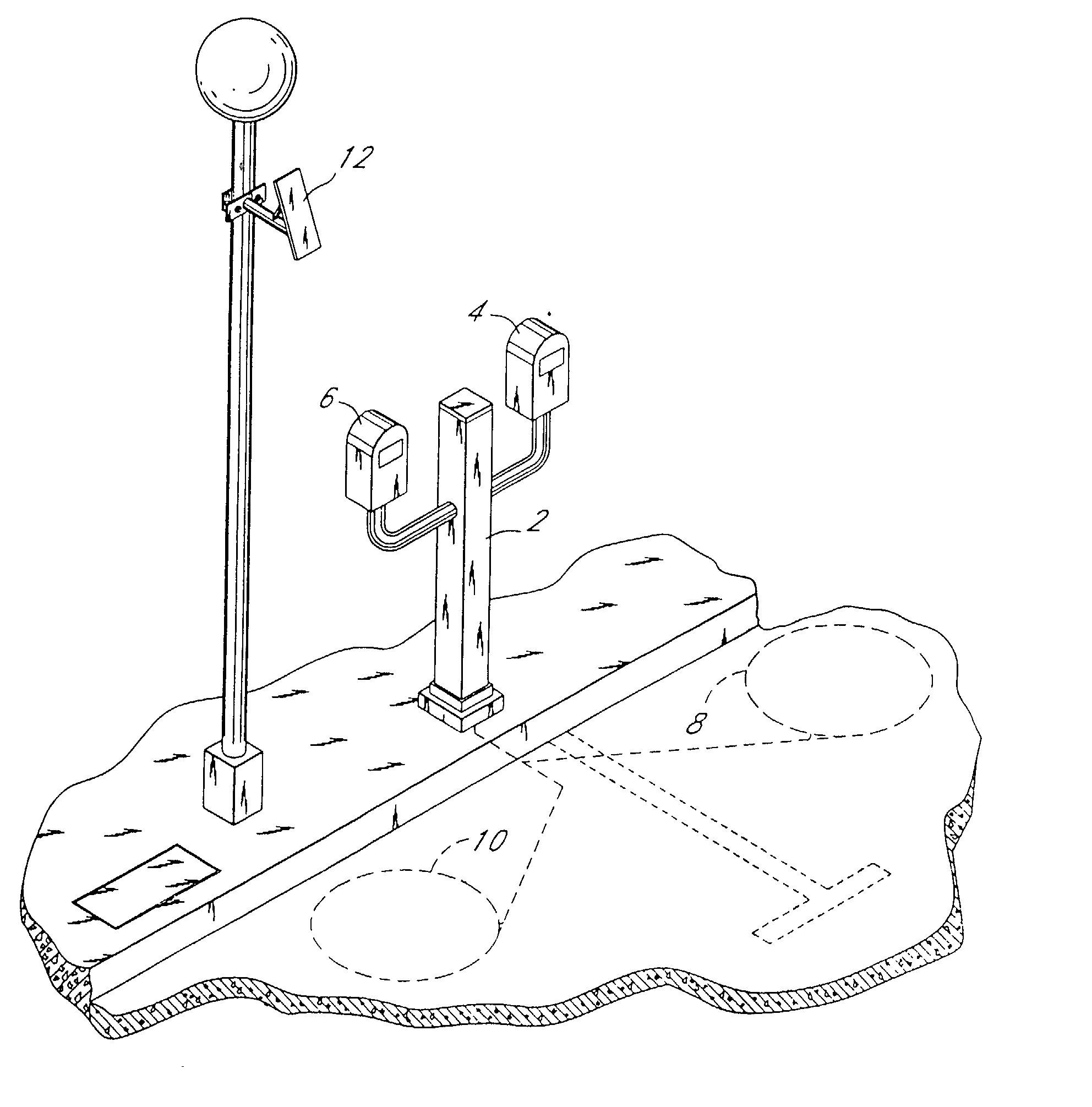
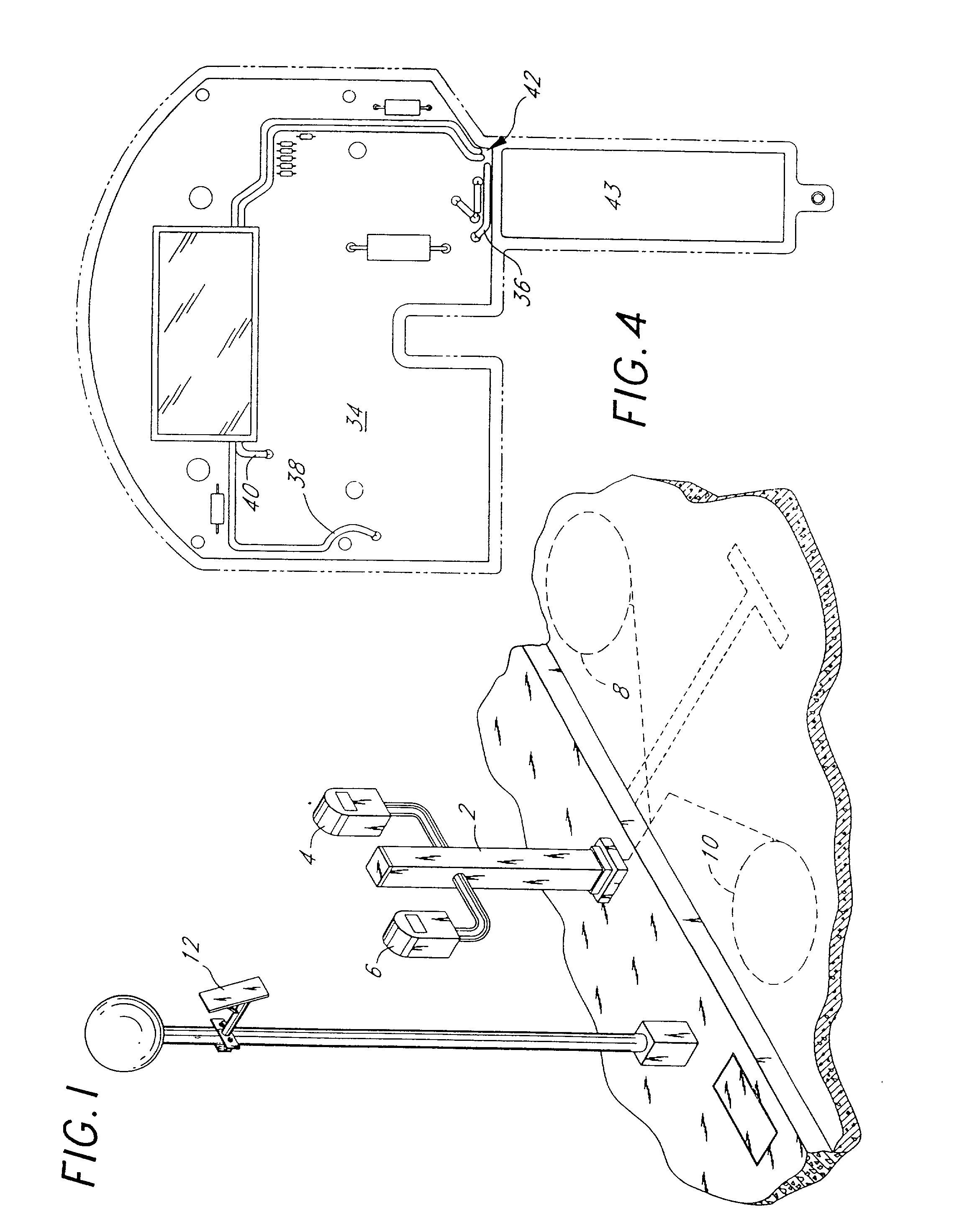
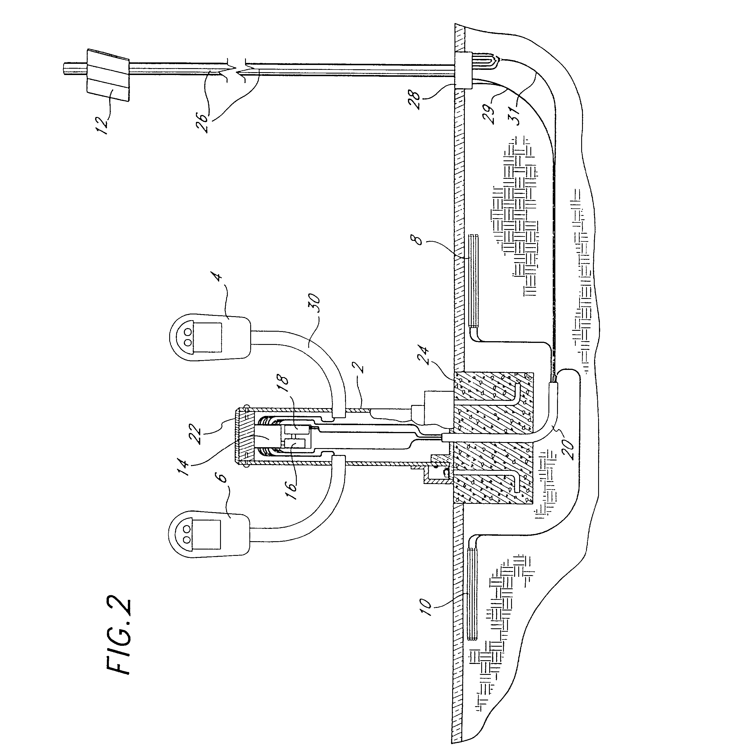
[0105] Turning in detail to the drawings, FIG. 1 illustrates an inductive loop-controlled, electronically operable parking meter system in accordance with the invention. The curbside parking meter stand 2 supports two electronically operable parking meters 4 and 6. The two inductive loops 8 and 10 are embedded in the pavement in the parking spaces corresponding to the parking meters. The right and left induction loops 8 and 10 are connected to the right and left electronically operable parking meters 4 and 6, respectively.

[0106] Inductive coils 8 and 10 each comprise several turns of insulated wire and are each wound to a specific size perimeter. The loops may be shaped as round, square, octagonal, etc. Further the inductive loops may be preformed prior to installation, or they may be wound with a single conductor wire using the saw cut in the pavement as the form. Leads 11 and 12 from the loops 8 and 10 are twisted together to form single pairs of conductors. The twisted pair 11 f...


PUM


Abstract

The field of the present invention is parking meters and more particularly to the use of electronically operated parking meters coupled with a sensor for positively sensing unobtrusively the presence or absence of a vehicle in a specified parking space controlled by the sensor and electronically operated parking meter. An induction coil mounted below the surface of the parking area is used to provide positive signals to the electronically operated parking meter and a cpu upon both the entrance of a vehicle into the parking space and the movement of the vehicle from the parking space. Moreover, the detecting system is battery operated and the battery life is extended by duty cycle operation of the detector system, whereby only a small portion of a detecting cycle is actually employed for detecting the status of the parking space.

Description

[0001] 1. Field of the Invention[0002] The field of the present invention is parking meters and more particularly to the use of electronically operated parking meters coupled with a sensor for positively sensing unobtrusively the presence or absence of a vehicle in a specified parking space controlled by the sensor and electronically operated parking meter. In the present invention an induction coil mounted below the surface of the parking area is used to provide positive signals to the electronically operated parking meter and a cpu upon both the entrance of a vehicle into the parking space and the movement of the vehicle from the parking space.[0003] Moreover, the detecting system is battery operated and the battery life is extended by duty cycle operation of the detector system, whereby only a small portion of a detecting cycle is actually employed for detecting the status of the parking space.[0004] 2. Related Art[0005] Parking meters have traditionally been used to raise revenu...

Claims


Application Information

Patent Timeline
IPC IPC(8): G07C1/30G07F17/24G08G1/042G08G1/14
CPCG07C1/30G07F17/246G07F17/248G08G1/042G08G1/14
Inventor POTTER, THOMAS R. SR.FERGUSON, RALPH C.
Owner FYBR
Learn More