Arrangement for determining the relative position of two bodies that are movable in relation to each other, and process for producing such an arrangement

Inactive Publication Date: 2002-09-19
REXROTH STAR
View PDF0 Cites 37 Cited by
  • Summary
  • Abstract
  • Description
  • Claims
  • Application Information

AI Technical Summary

Benefits of technology

0003] Consequently, it is an object of the invention in its first aspect to provide a way that makes it possible to av

Problems solved by technology

This is so because in the case of very long measuring tapes there is the risk that, in a built-in situation wherein the tape is located on a ve

Method used


Image

  • Arrangement for determining the relative position of two bodies that are movable in relation to each other, and process for producing such an arrangement
  • Arrangement for determining the relative position of two bodies that are movable in relation to each other, and process for producing such an arrangement
  • Arrangement for determining the relative position of two bodies that are movable in relation to each other, and process for producing such an arrangement

Examples


Embodiment Construction

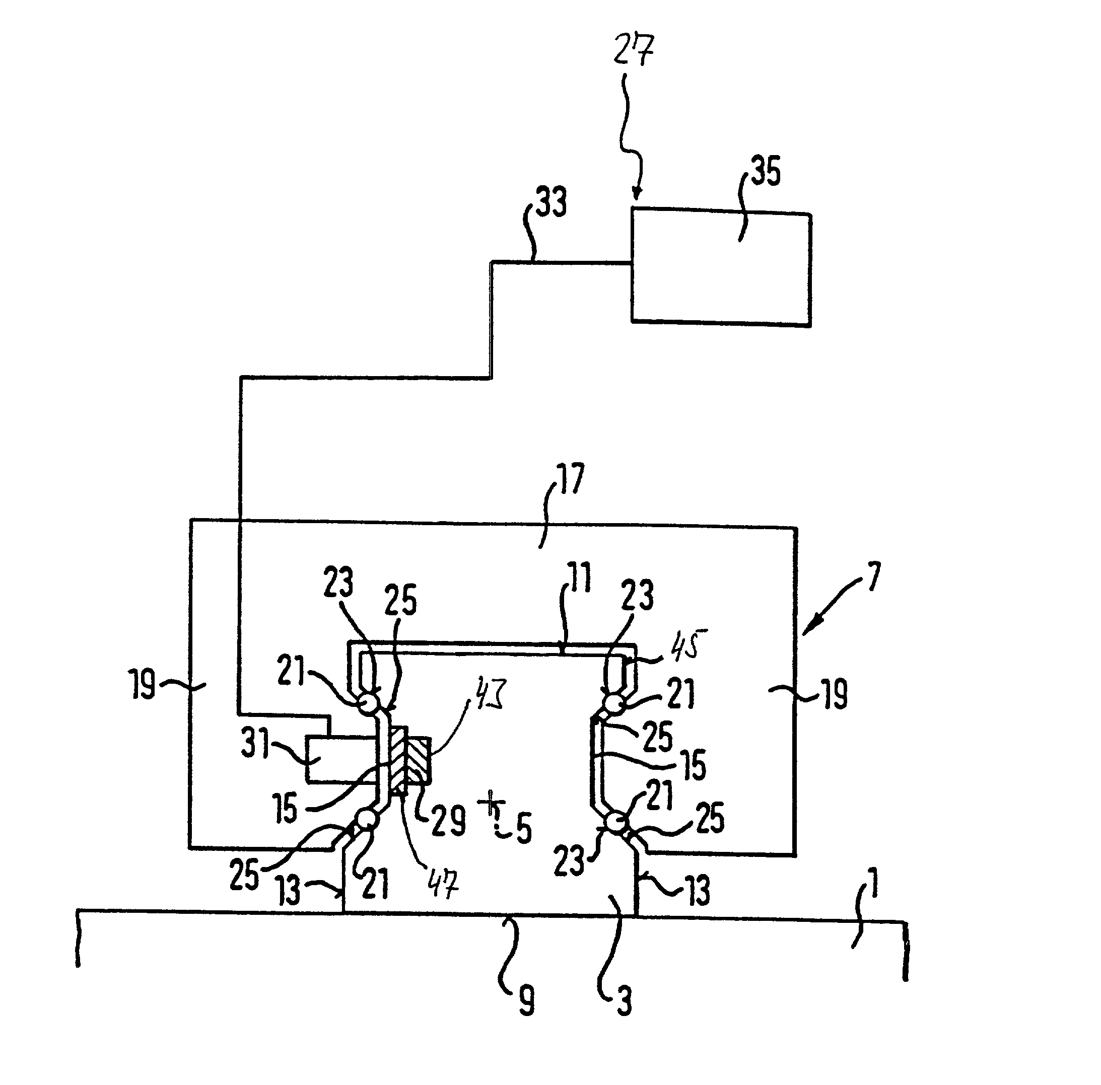
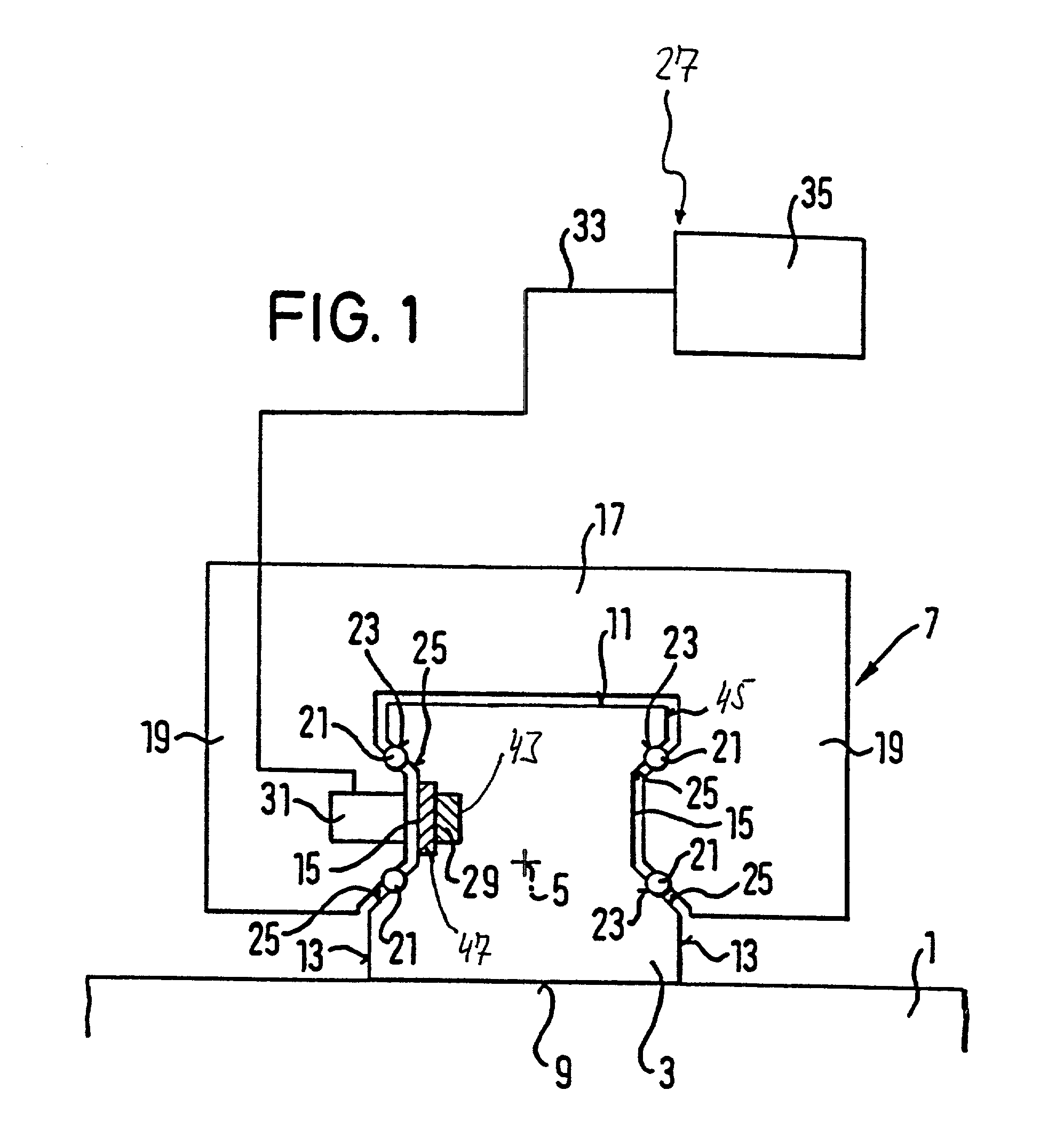
[0049] FIG. 1 shows a linear-guide arrangement with a guide rail 3 fastened on a support base 1 and a runner 7 guided in a mobile manner on the guide rail 3 along a rail longitudinal axis 5. The guide rail 3 has a fastening surface 9 with which it rests on the support base 1, a head surface 11 which lies opposite to the fastening surface 9, as well as two lateral surfaces 13 which connect the fastening surface 9 to the head surface 11. The lateral surfaces 13 of the guide rail 3 are each equipped with a trapezoidal-shaped recess 15. The guide rail 3 is rigidly screwed onto the support base 1 by means of threaded bolts (not shown), which are arranged at regular intervals along the longitudinal axis 5 of the rail and which traverse the guide rail 3, starting at the head surface 11.

[0050] The runner 7 envelops the guide rail 3 in an approximately U-shape, whereby its bridge region 17 lies adjacent to the head surface 11 of the guide rail 3 and its two leg regions 19, connected by the b...


PUM

PropertyMeasurementUnit
Lengthaaaaaaaaaa
Metallic bondaaaaaaaaaa
Responsivityaaaaaaaaaa

Abstract

In an arrangement for determining the relative position of two bodies (3, 7) that are movable relative to each other, a separate measuring tape (29) is attached to a first (3) of the two bodies (3, 7). The measuring tape includes at least one track of measuring markings, distributed in the longitudinal direction of the tape. The second (7) of the two bodies (3, 7) carries a sensor arrangement (31) which responds to the measuring markings and travels along the track, in the course of relative movement between the two bodies (3, 7). The measuring tape (29) is attached to the first body (3), at at least two attachment points that are arranged at a distance from each other in the longitudinal direction of the tape, and is elastically stretched between the attachment points in the longitudinal direction of the tape.

Description

BACKGROUND[0001] The invention concerns, in a first aspect, an arrangement for determining the relative position of two bodies which are movable in relation to each other. On a first body of the two, a separate measuring tape is arranged which features at least one track of measuring markings, distributed along the length of the tape. The second of the two bodies carries a sensor arrangement which responds to the measuring markings and which, in the course of relative movement between the two bodies, travels along the track.[0002] In general, one seeks to keep the measuring tape free of folds or distortions so that the accuracy of measurement is not impaired by unevennesses of the measuring tape, and so that, if the second body brushes closely over the measuring tape, the second body's motions are not hindered by undulations in the measuring tape. Occasionally, the position-determining arrangement is used in a working environment which is subject to relatively strong variations in t...

Claims


Application Information

Patent Timeline
IPC IPC(8): G01B7/00F16C29/00F16C29/06F16C41/00G01B11/00G01B21/00G01D5/14G01D5/16G01D5/245
CPCF16C29/005F16C29/0633G01D5/147G01D5/2457F16C41/00F16C41/007
Inventor BLATTNER, PETERSCHNOS, BRUNOKIRCHNER, HERBERT
Owner REXROTH STAR
Why Eureka
Try Eureka