Moving picture real-time communications terminal, control method for moving picture real-time communications terminal, and control program for moving picture real-time communications terminal

a real-time communication terminal and control method technology, applied in the field of moving picture communication, can solve the problems of inability to recognize, reducing the frame rate, missing frames of video image data, etc., and achieve the effects of improving image quality, reducing bandwidth, and increasing the bit rate of compression

Inactive Publication Date: 2006-11-30
FUJIFILM CORP +1
View PDF3 Cites 24 Cited by
  • Summary
  • Abstract
  • Description
  • Claims
  • Application Information

AI Technical Summary

Benefits of technology

[0006] The present invention has been contrived in view of the foregoing circumstances, an object thereof being to improve image quality, without losing smoothness in the movement of the video image, even if the transmission bandwidth of the network is reduced.
[0008] Preferably, the conversion unit converts the RGB video image signal into the YUV video image signal having a YUV 4:2:0 format; and the compression and encoding unit increases the bit rate of the compression and encoding of the Y signal, up to a maximum of 1.5 times, in accordance with the disconnection of the output paths of the U and V video image signals.
[0009] In order to attain the aforementioned object, the present invention is also directed to a control method for a moving picture real-time communications terminal, comprising: an input unit which inputs an RGB video image signal; a conversion unit which converts the RGB video image signal into a YUV video image signal including Y, U and V video image signals; a compression and encoding unit which digitally converts the YUV video image signal outputted from the conversion unit into moving picture data, and compresses and encodes the moving picture data; a communications unit which sends and receives the moving picture data compressed and encoded by the compression and encoding unit, in real time, to and from a communications terminal of another party connected through a network; a bandwidth estimation unit which estimates change in a bandwidth of the network; and a switching circuit which connects and disconnects output paths of the U and V video image signals from the conversion unit to the compression and encoding unit, the method comprising the steps of: disconnecting the output paths of the U and V video image signals by operating the switching circuit, in response to the change in the bandwidth estimated by the bandwidth estimation unit; and increasing a bit rate of compression and encoding of the Y signal by the compression and encoding unit, in accordance with the disconnecting of the output paths of the U and V video image signals.
[0011] According to the present invention, the video image signal is switched from color to black and white by disconnecting the output paths of the U and V signals of the YUV video image signal, and the bit rate of the compression and encoding of the Y signal is increased, by an maximum amount corresponding to the amount, of U and V data removed by this disconnection of the U and V signals. For example, if the conversion unit is converting the RGB video image signal into the YUV video image signal having the YUV 4:2:0 format, then by switching to a black and white image, the bit rate of the compression and encoding for the Y signal alone is increased up to a maximum of 1.5 times. In other words, even if the bandwidth is reduced, by switching the video image signal that is to be compressed and encoded to a black and white image signal, and then increasing the bit rate of the compression and encoding of the Y signal, it is possible, conversely, to improve the image quality. Therefore, there is no reduction in the number of frames, or development of “jerkiness” in the movement of the image, in response to a reduction in the bandwidth, as in the related art.

Problems solved by technology

When video images are exchanged mutually in real time between terminals which are connected through a communications network, such as that in a video telephone and a video conferencing system, there may be a problem in that the video image data has missing frames or the frame rate is lowered if image quality is prioritized (in other words, maintaining a high compressed bit rate in each frame unit).
For example, in a video telephone for sign language as used by persons with hearing difficulties, the facial expression and the manual gestures of the other communicating party are important, and if the observer sees a video image of the other party which does not display smooth movement due to missing frames, then it is not possible to recognize the changes in the facial expression, the mouth movements, and the manual gestures, of the other party, and hence it is difficult to understand the contents of the sign language.

Method used


Image

  • Moving picture real-time communications terminal, control method for moving picture real-time communications terminal, and control program for moving picture real-time communications terminal
  • Moving picture real-time communications terminal, control method for moving picture real-time communications terminal, and control program for moving picture real-time communications terminal
  • Moving picture real-time communications terminal, control method for moving picture real-time communications terminal, and control program for moving picture real-time communications terminal

Examples


Embodiment Construction

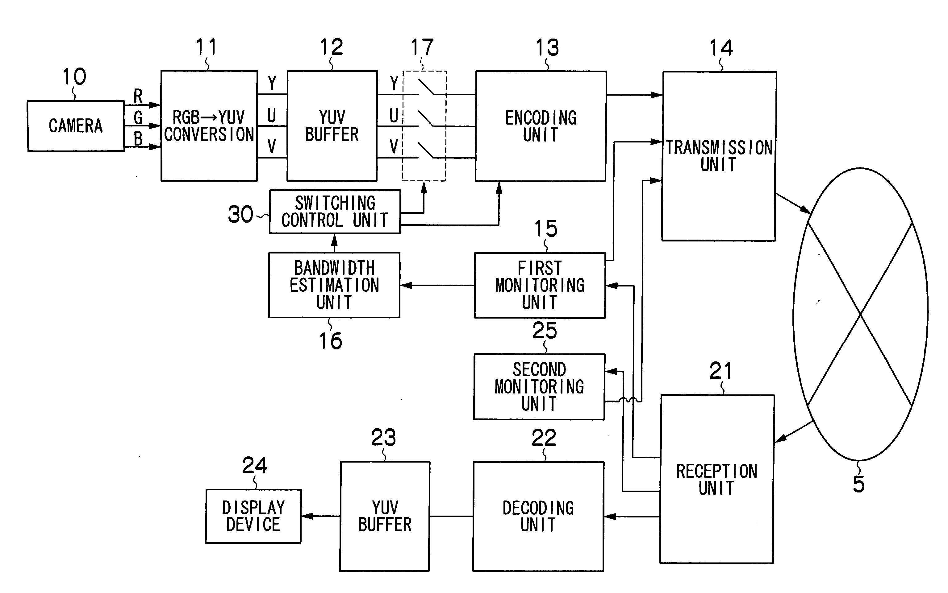
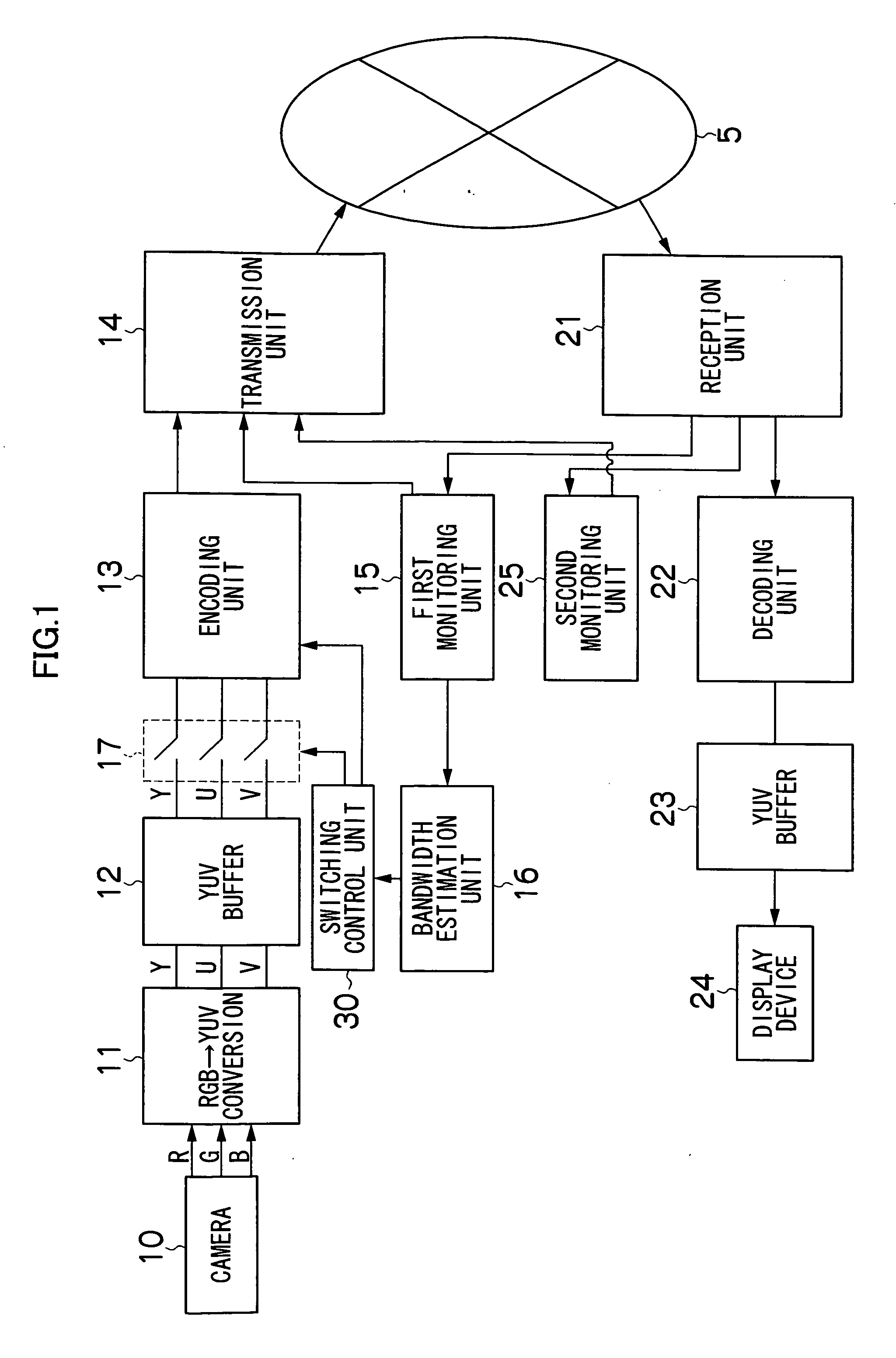
[0016]FIG. 1 is a block diagram of a communications terminal 100 according to a preferred embodiment of the present invention. This communications terminal 100 is connected through a network 5 to the communications terminal 100 of another communicator, having a similar composition. The communications terminal 100 converts a video image signal to a moving picture signal digitally compressed and encoded and sends the moving picture signal in the form of packets to the communications terminal 100 of the other party. At the same time, the communications terminal 100 receives, decodes and reproduces a moving picture that has been similarly digitally compressed and encoded, from the other party.

[0017] In order to simplify the description, the communications terminals 100 are described as being connected in a one-to-one correspondence (namely, a unicast configuration), but a multicast or broadcast configuration can also be possible. The connection path between the communications terminals...


PUM


Abstract

The moving picture real-time communications terminal comprises: an input unit which inputs an RGB video image signal; a conversion unit which converts the RGB video image signal into a YUV video image signal including Y, U and V video image signals; a compression and encoding unit which digitally converts the YUV video image signal outputted from the conversion unit into moving picture data, and compresses and encodes the moving picture data; a communications unit which sends and receives the moving picture data compressed and encoded by the compression and encoding unit, in real time, to and from a communications terminal of another party connected through a network; a bandwidth estimation unit which estimates change in a bandwidth of the network; a switching circuit which connects and disconnects output paths of the U and V video image signals from the conversion unit to the compression and encoding unit; and a switching control unit which disconnects the output paths of the U and V video image signals by operating the switching circuit, in response to the change in the bandwidth estimated by the bandwidth estimation unit, wherein the compression and encoding unit increases a bit rate of compression and encoding of the Y signal, in accordance with disconnection of the output paths of the U and V video image signals.

Description

BACKGROUND OF THE INVENTION [0001] 1. Field of the Invention [0002] The present invention relates to moving-picture communication, and more particularly to moving-picture communication through a network of varying bandwidth, and to technology which ensures prescribed image quality by switching between color moving pictures and black and white moving pictures. [0003] 2. Description of the Related Art [0004] In moving-picture communication, various technologies have been developed for dynamically adjusting the transmitted data volume in accordance with the bandwidth of the network environment. For example, Japanese Patent Application Publication No. 2002-77857 discloses that re-sequencing and / or selection of the data of respective elements in multimedia data is carried out on the basis of network information relating to the bandwidth, and the corresponding results are stored temporarily in a buffer. The transmission engine processes the multimedia data in accordance with these results...

Claims


Application Information

Patent Timeline
Patent Type & Authority Applications(United States)
IPC IPC(8): G06F15/00H04L47/80H04N11/04
CPCH04N7/141H04N19/164H04N19/156H04N19/115
Inventor SUZUKI, HARUYOSHI
Owner FUJIFILM CORP
Why Eureka
Try Eureka