
Pipe fitters lay out tool

a pipe fitting and tool technology, applied in the direction of distance measurement, instruments, using mechanical means, etc., can solve the problems of difficult to indicate the required angle on the pipe face, difficult to use, and difficult to find

Inactive Publication Date: 2002-10-03
KNEIPP MATT C
View PDF0 Cites 10 Cited by
  • Summary
  • Abstract
  • Description
  • Claims
  • Application Information

AI Technical Summary

Problems solved by technology

Although Mr. Morans square is useful for squaring pipe ends or flanges., It lacks in the ability to indicate required angles other Than horizontal, vertical or 45 degrees on a pipe face easily.
Although combination type lay out tools may be more versatile allowing squaring of pipe flanges or other capabilities, they are more complex to use as they require adjustments to squaring arms and or additional layout tools to complete basic lay out process as required for generating cut geometry guide lines on pipe sections.
This tool is one of several more complex approaches to laying out cut line geometry Systems of this type are not very compact however as they usually consist of a precision protractor equipped rotational point which attaches the tool to it's base, and a long articulated arm equipped with a marker that can access the entire circumference of a pipe section
Although tools of this type; when set up properly and properly attached as required to the pipe or work piece being laid out have the ability to accurately indicate cut geometry, the proper angle and the location of the necessary cuts without templates or ordinate tables, they are not light weight or rugged. requiring that they generally be used in large shop environments or areas that do not restrict movement of the tool, the articulated arm or it's component part

Method used


Image

  • Pipe fitters lay out tool
  • Pipe fitters lay out tool
  • Pipe fitters lay out tool

Examples


Embodiment Construction

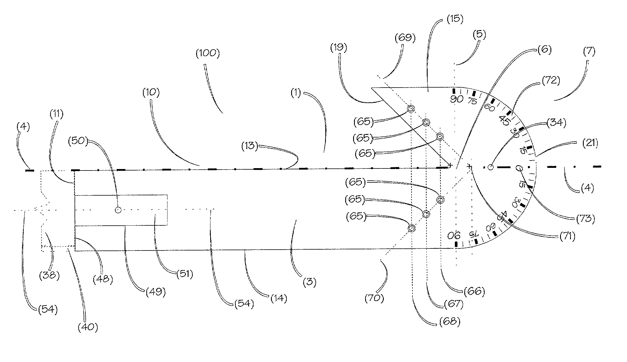
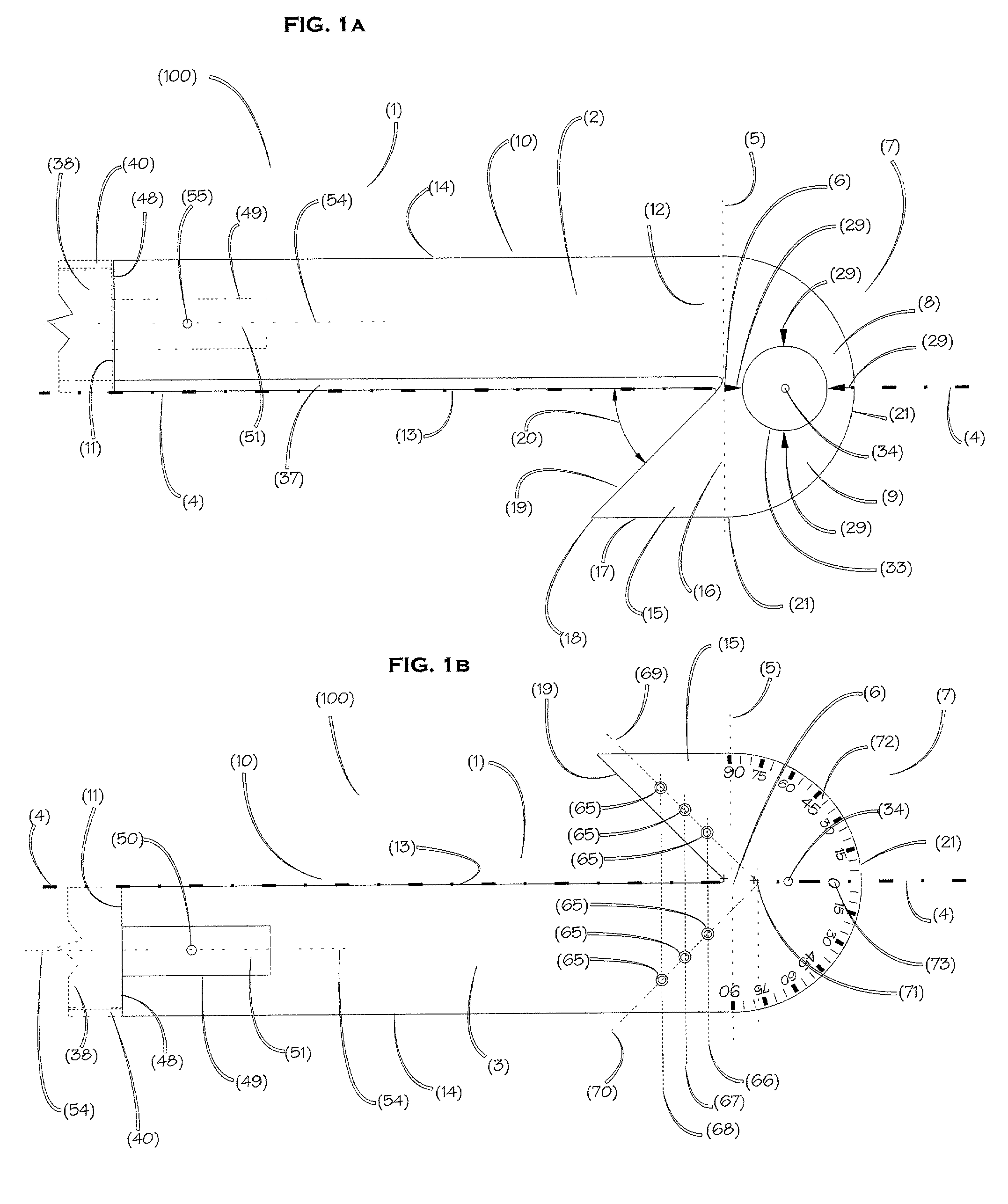
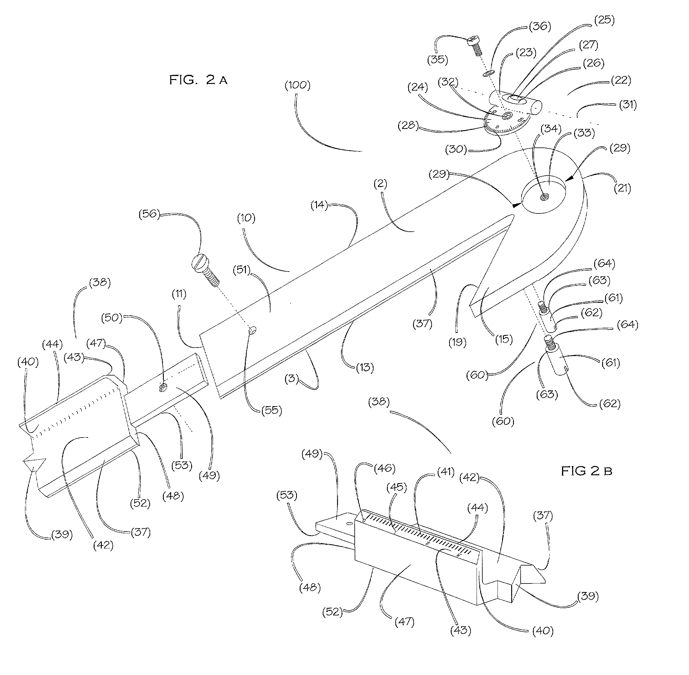
[0023] Referring to FIGS. 1a and b where 1a shows the top surface and 1b shows the bottom surface of the preferred embodiment of Pipe fitters layout tool, here in referred to as the tool 100. Tool 100 is comprised of a one piece Fame 1 fabricated from lightweight material such as aluminum approximately 3 / 8" thick.

[0024] Said one piece frame 1 being of irregular geometry can best be described by identifying three basic geometric shapes that comprise the shape of frame 1. The shapes are, a half circle consisting of two quadrants, an elongated rectangle and an Isosceles triangle It should be noted for the purpose of this description that three shapes are used to define the single overall shape of frame 1. The shapes are directly adjacent to each other and relative to two lines that are perpendicular to each other. The two lines are, the longitudinal centerline 4 of frame 1 and datum line 5 which crosses substantially perpendicular to longitudinal centerline 4 at point 6. The first basi...


PUM


Abstract

A simplified light weight squaring tool used by pipe fitters in conjunction with templates or pipe fitters tables for laying out pipe intersect angles and geometry as required for cutting and joining pipe of various sizes at various angles. A rugged tool intended primarily for on sight use, comprises a self centering straight edge arranged for guiding and scribing of lines on flat surfaces, curved surfaces or across the diameter of a pipe face, an integral adjustable protractor level, allowing for fast and accurate perpendicular and angular orientation of the straight edge when used in the vertical plane and a self aligning extension arranged for expanding the capacity of the squaring tool and transcribing angular lines from the face of pipe sections onto the circumference or outside diameter of pipe parallel to longitudinal centerline of the pipe as required for layout

Description

[0001] The present invention relates to tools used In the fabrication of pipe and more particular to a simple tool used for generating geometry and layout lines required for precise cutting and joining of pipe sections in preparation for welding.[0002] Oftentimes, due to pipe size, complexity of required joint intersect angles and final configuration of a piping system or run as it is commonly referred to, it is impractical to join the various sections of pipe by means of threaded ends requiring joints and pipe sections to be mated by annular weld beads.[0003] To insure proper fit and joint integrity of pipe sections that intersect at various angles forming a particularjoint for welding, each of the pipe sections or components are required to be cut at a specific geometry that will provide for proper fit of one to the another. The specific geometry of the cut required on either of the pipe sections is dependent upon the size and or respective size differences of each pipe component ...

Claims


Application Information

Patent Timeline
IPC IPC(8): G01B3/56G01B5/24
CPCG01B5/24G01B3/563
Inventor KNEIPP, MATT C.
Owner KNEIPP MATT C
Learn More