
Color dependent luminance processing

a luminance processing and color-dependent technology, applied in the field of digital image processing, can solve the problems of unfavorable yellow color cast and adverse effects on another portion of the imag

Inactive Publication Date: 2002-10-31
MONUMENT PEAK VENTURES LLC
View PDF0 Cites 2 Cited by
  • Summary
  • Abstract
  • Description
  • Claims
  • Application Information

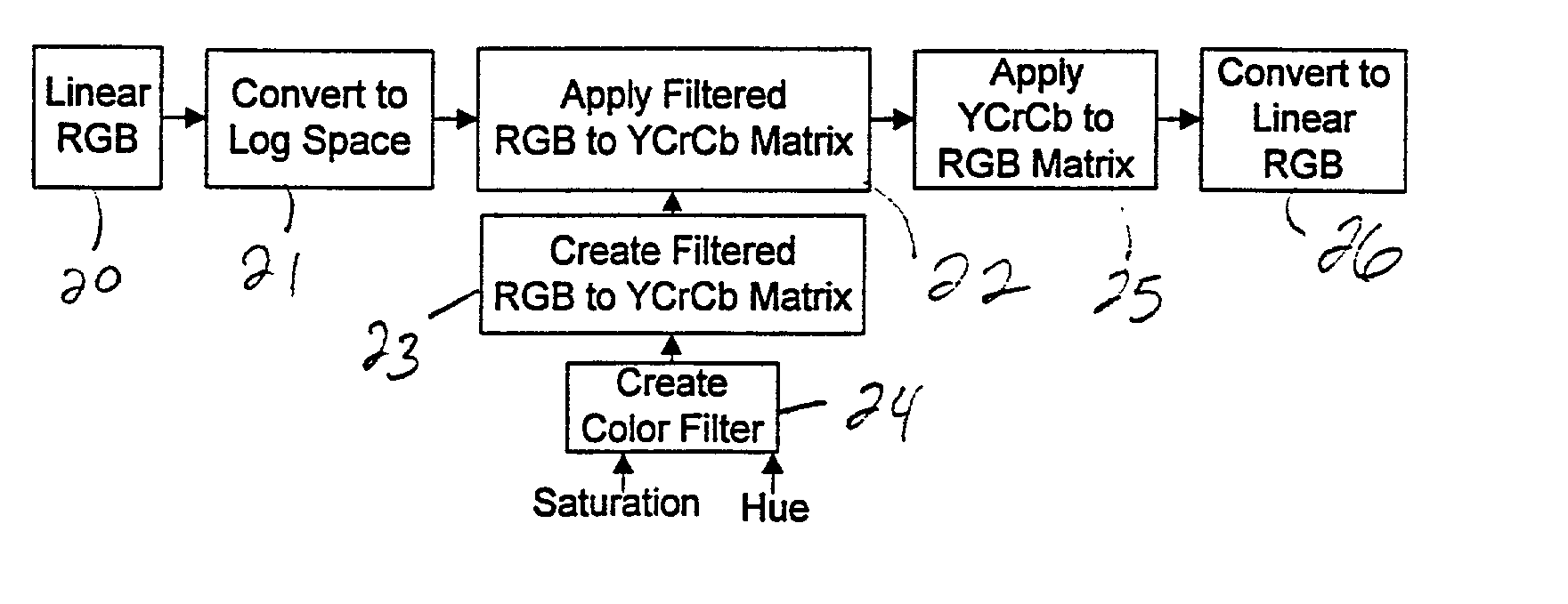
AI Technical Summary

Benefits of technology

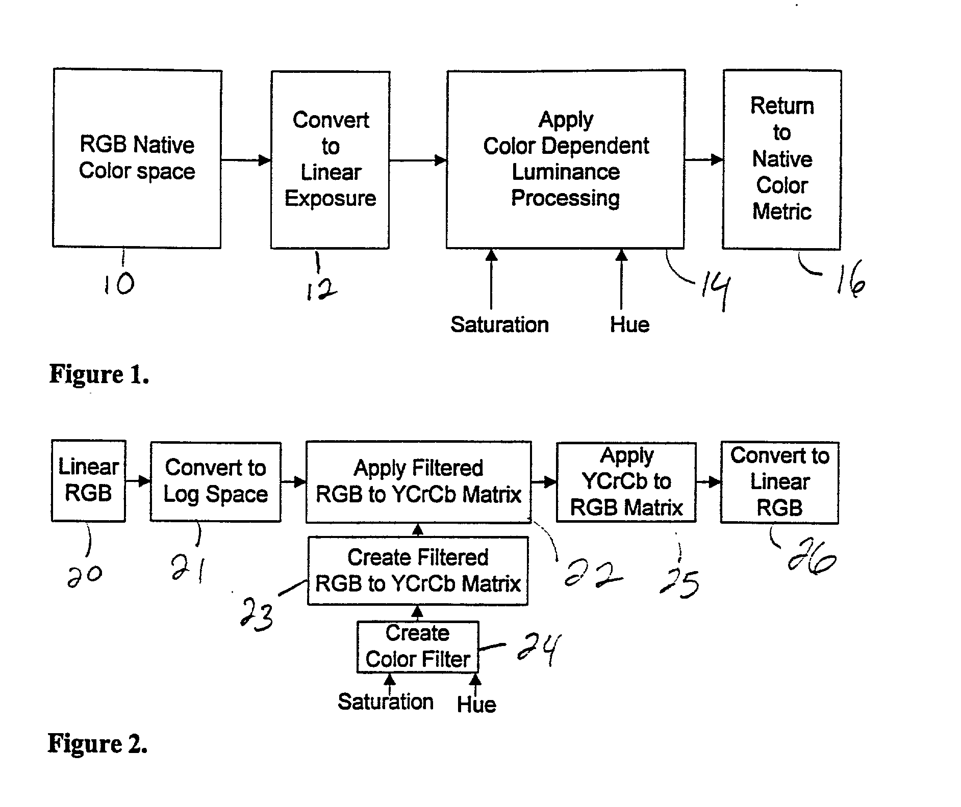
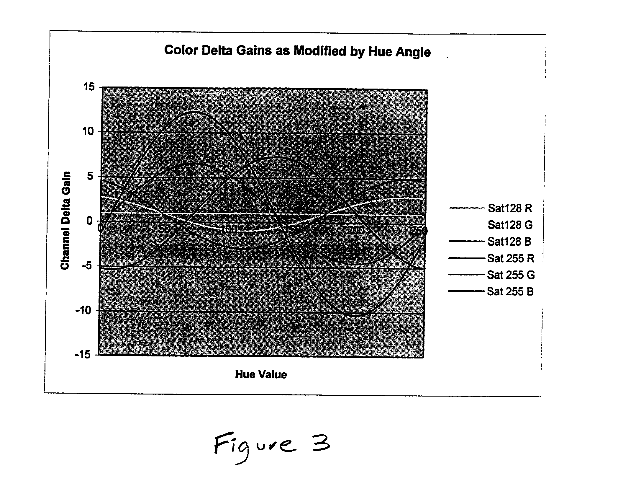
[0007] With the invention, color filters can be synthesized for a digitized color image and applied to the image to modify the contrast without imparting a color cast. Further, the invention allows unrenderable portions of the image that are too bright or too dark to be modified based upon chrominance so as to bring the unrenderable portions into a mid-tone range and make them renderable.[0008] Using the invention, the filter applied (e.g., the calculation of the luminance channel) could optionally be a function of the color coordinates described by the chrominance, the pixel's location in the image, the proximity to other colors / hues, or results from other image analysis / image understanding algorithms. Thus, the invention allows different filters to be selectively applied to different portions of the image. For example, the calculation of blue regions may suppress blue to darken a blue sky, while a flesh tone region may use a different filter to alter contrast differently in those regions.[0009] The foregoing and other objects, aspects and advantages will be better understood from the following detailed description of a preferred embodiment of the invention with reference to the drawings, in which:[0010] FIG. 1 is a schematic flow diagram of one embodiment of the invention;[0011] FIG. 2 is a schematic flow diagram of one embodiment of the invention;[0012] FIG. 3 is a graph illustrating color delta gains as modified by hue angle;[0013] FIG. 4 is a schematic diagram of a system embodiment of the invention; and[0014] FIG. 5 is a schematic diagram of a computer system embodiment of the invention.

Problems solved by technology

However, when the same filters are applied to color photography an undesirable yellow color cast can result.
While the filter may change one portion of the image in a desired fashion, there is a possibility that another portion of the image will be adversely affected.
Therefore, conventional filters always present a trade-off between desirable and undesirable effects.

Method used


Image

  • Color dependent luminance processing
  • Color dependent luminance processing
  • Color dependent luminance processing

Examples


Embodiment Construction

[0015] The invention achieves the foregoing advantages by converting an image from red-green-blue (RGB) space into luminance and chrominance space, filtering (based upon color) the luminance channel, and returning the image to RGB space, to allow different color filters to be selectively applied to an image. Typically, the luminance channel is created from a linear combination of the red, green and blue channels in a way that mimics the photopic efficiency function. However, with the invention, the luminance channel is created from a combination (linear or non-linear) of red, green and blue as though they pass through a color filter, so as to achieve the desired luminance contrast. This new luminance channel is then re-combined with the chrominance channels and converted back to RGB.

[0016] An optical color filter selectively attenuates the luminance of the image based upon wavelength of light reflected from an object. Theoretically, any region or combination of regions of the color ...


PUM

PropertyMeasurementUnit
focal distanceaaaaaaaaaa
luminanceaaaaaaaaaa
coloraaaaaaaaaa

Abstract

A method and structure for developing a photographic image from a camera, filtering the image, and developing the image. Filtering of an image entails separating the image into a luminance channel and chrominance channels, alternating the luminance channel by saturation and hue to produce the altered luminance channel and recombining the chrominance channels and the altered luminance channel. The hue controls the color of filtering and the saturation controls the strength of the filtering. Prior to separating and converting the linear exposure is converted to a logarithmic space. This conversion of linear exposure to logarithmic space allows the luminance's channel to be altered independently from the chrominance channels. The alteration creates a filtered RGB to YCrCb matrix and applying the matrix to the logarithmic space produces a filtered logarithmic space. The invention recombines the YCrCb to RGB matrix to the filtered logarithmic space.

Description

[0001] 1. Field of the Invention[0002] The invention relates generally to the field of digital image processing and more particularly to luminance processing that is based upon color dependence.[0003] 2. Description of the Related Art Color filters are used in black and white photography to modify contrast in the captured image. For example, yellow filters are used in outdoor black and white photography to darken the sky and reduce haze. However, when the same filters are applied to color photography an undesirable yellow color cast can result.[0004] Further, the filters used in photography are conventionally applied to the image globally. In other words, a certain color (or combination color) filter is applied to the entire image. While the filter may change one portion of the image in a desired fashion, there is a possibility that another portion of the image will be adversely affected. Therefore, conventional filters always present a trade-off between desirable and undesirable ef...

Claims


Application Information

Patent Timeline
Patent Type & Authority Applications(United States)
IPC IPC(8): H04N1/60H04N1/62
CPCH04N1/6005H04N1/62H04N1/6075
Inventor PRENTICE, WAYNE E.
Owner MONUMENT PEAK VENTURES LLC
Learn More